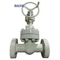
Design Requirements for Main Parts of Nuclear Power Valves (Part Two)
(2) C2 valves
The body of the C2 valve can be made of forged steel and cast steel. When the welding seam on the pressure-bearing boundary can be inspected by radiography, the forged welding structure can also be used. The connection between the valve body and valve bonnet of valves with different pressure adopts pressure self-sealing and sealed bolt connection. For the pressure of 5.0MPa and above, concave-convex mating surfaces and fully embedded gaskets are used. Concave-convex gaskets, sealing lip type and bolts should be adopted for the connection between the valve body and bonnet if required. The upper sealing surface of the valve bonnet and stem can be built up welded with hard alloys on the surface. The sealing surface of the non-alloy steel bonnet shall be built up welded with stainless steel.
The stem should have no deflection. The surface should be ground, and the diameter tolerance of the stem in contact with the packing should be less than 0.1 mm. The roughness of the inner surface of the stuffing box R should be 1.6um. One surface of the sealing surface (valve seats or valve plates) is built up welded with hard alloys, and the other surface is built up welded with hard alloys when the pressure is greater than and equal to 6.8MPa (400LB); stainless steel should be built up welded when the pressure is greater than and equal to 5.0MPa (300LB).
(3) C3 valves
The valve body of the C3 valve can be made of forged steel, cast steel or rolled steel. The valve body and bonnet shall be connected by sealed bolts. The gasket can be non-embedded. The upper sealing surface of the valve bonnet and valve stem can be built up welded with hard alloys. The sealing surface of the valve with the pressure of 6.8MPa (400LB) should be surfacing welded with cemented carbide. The sealing surface of the valve with the pressure of 5.0MPa (300LB) and below and the hardness of valve plates and valve seats which have a big difference should be surfacing welded with stainless steel.
The stem should have no deflection, and the surface should be ground. The diameter tolerance of the stem in contact with the packing should be less than 0.1 mm, and the surface roughness R should be 0. 8μm. The surface roughness of the stuffing box R.m should be 1.6μm.
2.3 Check valves
In general, the regulations on valve bodies and bonnets as well as their connections among globe valves of small diameters, globe valves of large diameters and gate valves are also applicable to lift check valves and swing check valves.
(1) Lift check valves with small diameters
The guiding part of the small-diameter lift check valve stem should have enough length to allow the disc to move freely without hindrance. There should be a balance for the hole guide mechanism to avoid the piston effect.
The sealing surface of C1 lift check valve discs and valve seats should be built up welded with hard alloys. It is forbidden to use conical seats and conical counter ring seats. The sealing surface of C2 lift check valves of pressure I should be built up welded with hard alloys. According to operating conditions, synthetic rubber seats can be adopted as another sealing surface for non-nuclear standard valves. Valves of pressure III do not require hard alloy surfacing on the surface. Synthetic rubber seats can be used as a sealing surface. If it is separated, it can be welded.
(2) Swing check valves
The surface of the seat and disc of the C1 and C2 valves of each pressure group of the swing check valve and the C3 valve of the pressure group II should be welded with hard alloys. The sealing surface of the C3 valve of the pressure subgroup should be welded with stainless steel or hard alloys. Regardless of whether there is a medium in the valve, the disc should be able to return to the closed position by its weight. If possible, in the fully open position, the disc should be immersed in the medium inside the valve. The connecting mechanism of the valve disc and the rocker should have enough swing space to ensure the accurate return of the valve disc. The disc cannot rotate relative to the rocker. The rocker pins of nuclear-standard valves are not allowed to penetrate the valve body. If the valve seat is separated, it can be welded.
2.4 Ball valves
Under normal circumstances, the ball valve should be designed as a straight-through type, that is, the valve port should not be less than 80% of the cross section of the pipe. The valve body can be made of cast steel, forged steel, rolled or forged profiles. The valve stem should be inserted into the ball, and a safety device should be provided to prevent the ball from rotating relative to the valve stem. The valve stem should be aligned with the guide bushing in the valve body. The sealing surface of the valve stem should be ground. The roughness of C1 and C2 valves should be 0.4μm, and C3 valves 0.8μm. The O ring should be adopted for the sealing of the valve stem. The surface roughness of the sphere should be 0.4μm. The valve seat should be made of synthetic rubber. There should be two limit devices for the movement of the sphere, one for the fully open position and the other for the closed position.
3. Universal design
3.1 The opening and closing of valves
The valve should meet the requirement of opening and closing at least 4 times per day, and can withstand opening and closing 1500 times. Except for planned maintenance due to lubrication, re-tightening of the packing, replacement of the packing when abnormally damaged, and re-tightening of bolts if necessary, the valve should work continuously for at least 10 years. The pressure-bearing shell components require to have a design life of 40 years.
3.2 Operating pressure difference
The operating temperature of non-alloy steel and austenitic stainless steel valves at room temperatures and chrome alloy steel valves at an operating temperature of 400°C shall have an operating pressure difference (OP) equal to the maximum allowable working pressure unless it is specified in the equipment technical specifications.
3.3 Manual transmission
The transmission device of the manual valve should be able to open or close the valve when the pressure difference is equal to the operating pressure difference OP. The total operating force of the handwheel during the full stroke should not be greater than 300N, and at the beginning and end of the stroke, it should not be greater than 600N. Deceleration devices are allowed. Whether a deceleration device is used, the valve should not be permanently deformed when the tangential operating force of the manual transmission device is equal to 900N. The sealing surface of the globe valve should not be damaged.
The total operating force of the handwheel of the spare manual transmission device of the pneumatic valve shall not exceed 300N in the full stroke, and 600N at the beginning and end of the stroke. The spare manual transmission device of the electric valve shall comply with the requirements of the "Electric Devices of Valves for PWR Nuclear Power Plants".
3.4 Pressure drop coefficient
When the valve is fully open, the pressure drop coefficient (L/D) of the gate valve and ball valve should be less than 13, the globe valve and three-way valve 140, the swing check valve and the diaphragm valve 135, the regulating valve and lift check valve 340.
3.5 The connection between the valve and pipeline
Welding, flange and thread connections should be adopted except for special requirements.
(1) Welding
Socket welding is used to connect valves with a size smaller than and equal to DN25 (1IN) and pipes. Butt welding is used for the connection between valves greater than and equal to DN25 and pipelines.
(2) Flange connections
The flange should meet the requirements of ASME B16.5 "Pipeline Flanges and Flange Fittings". Sealing welding, for example, sealing lip welding should also be used when a flange is adopted on the circuit that transports the radioactive medium.
(3) Thread connections
The compressed air system for non-instrument air can be connected by threads.
Send your message to this supplier
Related Articles from the Supplier

Design Requirements for Low Temperature Globe Valves
- Apr 14, 2015


Xinhai Gate Valve Design Features
- Sep 05, 2013
Related Articles from China Manufacturers
Design Requirements for Low Temperature Globe Valves
- Sep 23, 2016

Design Requirements for Solar Panel Control Systems
- Aug 24, 2024
Design Steps and Requirements for Mould Sample
- May 29, 2015
Requirements for Die Casting Design
- Nov 24, 2015
Safety Design Requirements of Valves
- Aug 04, 2017
Related Products Mentioned in the Article
- Address: Xinhai Industry Zone, Sanqiao, Oubei, Wenzhou, Zhejiang, P. R. China.
- Phone: +86 577 6699 3222
- Business Type: Industry & Trading, Manufacturer,
Supplier Website
Source: https://www.valvemanufacturer.net/design-requirements-for-main-parts-of-nuclear-power-valves-part-two.html