Nuclear-Grade Bellows Globe Valves for Hard-to-Access Areas in Nuclear Power Plants
This paper presents the detailed structural design of a nuclear-grade bonnetless bellows globe valve. Design verifications—including flow characteristics, structural stiffness, and seismic performance—were conducted to verify compliance with the latest Hualong One nuclear power technology standards. In addition, through a planned manufacturing process for this valve model, the study provides a comprehensive solution for bellows globe valves used in areas of nuclear power plants that are inaccessible to routine maintenance.
1. Overview
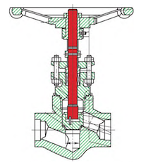
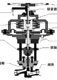
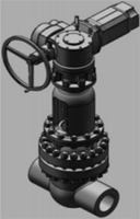
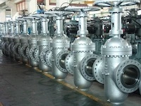
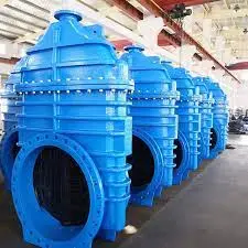
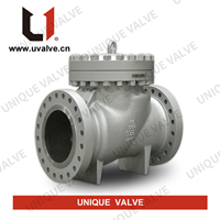
Certain areas of nuclear power plants are inaccessible for routine maintenance. Valves installed in these zones are critical equipment; any leakage cannot be corrected through online intervention and may cause a unit trip or reactor failure, posing significant risks to plant operation. These valves are typically installed in critical areas such as R-buildings, hydrogen explosion zones, red zones, primary instrument lines, and high-energy environments outside the containment. Bellows globe valves use bellows assemblies as sealing elements to prevent leakage of the process medium through the packing. They offer several advantages, including highly reliable sealing, long service life, strong corrosion resistance, broad applicability, and ease of installation, making them widely used in nuclear facilities. Based on long-term operational experience in nuclear power plants, valves used in maintenance-inaccessible areas are now held to stricter requirements for sealing performance and operational stability. For bellows globe valves in these locations, further reductions in leakage risk and improvements in maintenance efficiency are essential. Currently, the development of nuclear-grade bellows globe valves is highly advanced both domestically and internationally, with well-established designs and comprehensive structural research. Figures 1(a), (b), and (c) illustrate typical technical solutions for such valves from a nuclear valve manufacturer. Most designs incorporate at least one welded joint, complicating disassembly and emergency maintenance. This paper uses the nuclear-grade second-stage electric bellows globe valve (model SJXSSB0025SAG) as a case study. By detailing its structural design, design verification, and manufacturing process, this study demonstrates that the newly developed bonnetless nuclear-grade bellows globe valve meets the latest Hualong One nuclear power technology requirements and is suitable for long-term, stable operation in maintenance-inaccessible areas of nuclear power plants.
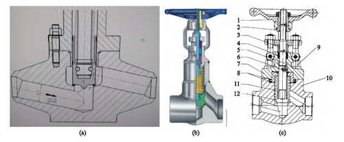
Figure 1. Typical designs of bellows globe valves: (a) Option 1, (b) Option 2, (c) Option 3
2. Structural Design
Bellows globe valves are particularly well suited for applications in areas inaccessible to routine maintenance, significantly reducing the risk of center flange leakage. Key design objectives include minimizing valve leakage risk and reducing valve maintenance time. The 'bonnetless deep-hole welding + MMC sealing ring' design proposed in this paper features a stuffing box integrated into the upper joint of the bellows. A graphite sealing ring (MMC), which is a metal-to-metal composite sealing structure, is used between the bellows assembly and the valve body. This design eliminates the bonnet and center flange fasteners by integrating the stuffing box and the bellows upper joint into a single unit, resulting in a more compact structure with reduced valve height and weight. The combination of the graphite sealing ring and the MMC structure in the sealing area offers dependable sealing performance. Furthermore, the valve stem retains its blowout-proof capability even when the pressure plate fasteners are loosened. One drawback of this design is that the deep-hole welding structure in the valve body complicates the overlay welding process. The final design of the nuclear-grade electric bonnetless bellows globe valve prototype is presented in Figure 2, with its key design parameters summarized in Table 1. The valve body utilizes a monolithic forged design characterized by a large diameter and deep-bore structure. The stem features a lift-rod design combined with an anti-rotation mechanism to reduce stem rotation effects, minimizing wear on the stem and packing and preventing leakage. Sealing at the upper joint of the bellows is achieved by an MMC sealing ring, with controlled compression of the graphite sealing ring against the MMC sealing boss providing a dependable seal in this critical area. The stem sealing system utilizes a dual-seal configuration, consisting of metal bellows and packing, to prevent external leakage and reduce environmental impact. The bellows assembly is secured to the valve body using a ring of evenly distributed nuclear-grade fasteners. To prevent loosening caused by vibration and fluctuations in temperature and pressure, 'ground-lock' anti-loosening pads are installed. As shown in Figure 2, the nuclear-grade electric bonnetless bellows globe valve’s overall design includes a test process flange, with a stuffing box installed at the upper joint of the bellows to enhance the valve’s compactness.
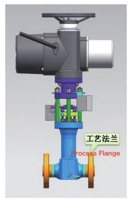
Figure 2 Nuclear-grade electric bonnetless bellows valve
Table 1. Design Parameters for Nuclear-Grade Bellows Globe Valve
|
Parameter |
Specification |
|
Valve Model |
SJXSSB0025SAG |
|
Nominal Diameter |
DN25 |
|
Design Temperature |
360°C |
|
Operating Temperature |
343°C |
|
Design Pressure |
21.4 MPa |
|
Operating Pressure |
17.13 MPa |
|
Pressure Rating |
1950 LB |
|
Safety Class |
2 |
|
Specification Level |
2 |
|
HAFJ0066 Classification |
SC-2 |
|
Seismic Qualification Level |
SSE1 |
|
Seismic Resistance Grade |
SSE1 |
|
Media |
Reactor Coolant |
|
Connection Type |
Butt Weld |
|
Inlet/Outlet Pipe Size |
φ33.4 × 6.35 mm / φ33.4 × 6.35 mm |
|
Warranty Requirements |
(To be clarified based on context) |
The gland of the packing assembly is inserted into the compression plate, with its outer diameter matching the inner diameter of the plate's bottom hole (Figure 3). This configuration guarantees a consistent clearance between the compression plate’s center hole and the valve stem, thereby effectively preventing friction due to uneven loading on the plate. The valve employs a modular design concept to facilitate rapid maintenance. Standardized components ensure interchangeability among parts of identical specifications. The modular design of the valve’s functional components, combined with the removable column structure and the toothed interface of the actuator, enables quick assembly and disassembly of the valve, as illustrated in Figure 4.
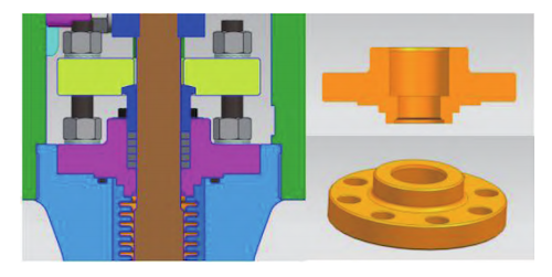
Figure 3: Schematic diagram of the pressure plate, compression sleeve, and upper bellows connector
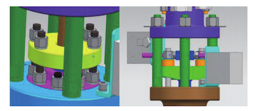
Figure 4: Packing assembly and removable column structure
3. Design Verification
The design verification process for the nuclear-grade second-stage bellows globe valve comprises two main components: fluid dynamics verification and mechanical performance verification.
Fluid design verification focuses on evaluating the valve’s flow capacity, with target values of C≥7.31 and L/D≤340L.
Mechanical design verification comprises:
- Natural frequency verification (≥ 33 Hz)
- Seismic performance verification
3.1 Valve Flow Capacity Verification
In accordance with the methodologies specified in GB/T 30832 and TP410, the valve’s flow capacity was assessed through computational fluid dynamics (CFD) analysis using CFDesign software. The flow coefficient (C) was calculated and converted into an equivalent length-to-diameter ratio (L/D) to verify compliance with the design requirements (C ≥ 7.31, L/D ≤ 340). Figures 5(a) and 5(b) present the contours of absolute velocity and static pressure distribution within the valve, respectively.
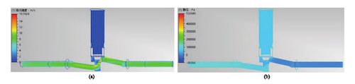
Figure 5. Contours of (a) Absolute Velocity and (b) Static Pressure Distribution
The calculated average flow coefficient of the nuclear-grade second-stage bellows globe valve is 9.2, with an equivalent length-to-diameter ratio (L/D) of 195. The results are summarized in Table 2.
Table 2. Average Flow Coefficient of the Nuclear Second-Stage Bellows Globe Valve
|
Parameter |
Value |
|
Flow Coefficient (Gi) |
9.09 |
|
Flow Coefficient (Grang) |
9.24 |
|
Average Flow Coefficient |
9.20 |
|
Pipe Inner Diameter (D) [mm] |
20.7 |
|
Maximum Flow Coefficient |
9.31 |
|
Friction Coefficient |
0.024 |
|
Equivalent Length (L/D) |
195 |
|
Valve Opening |
100% |
Flow Performance Under Different Inlet Flow Rates
|
Inlet Flow Rate [m³/h] |
ΔP (Inlet-Outlet Pressure Difference) [kPa] |
|
6 |
58.24 |
|
8 |
100.18 |
|
10 |
154.32 |
3.2 Natural Frequency Design Verification
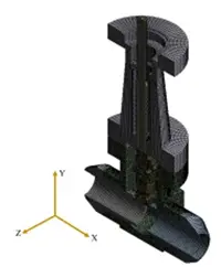
The valve's mode shape reflects the natural vibration characteristics of the valve structure as a whole. Finite element analysis (FEA) was used to determine the modal characteristics within the valve's susceptible frequency range, including the first-order natural frequency. ANSYS finite element simulations show that the valve's first-order natural frequency is 46.1 Hz, which meets the design requirement of ≥33 Hz. This indicates that the valve structure has good rigidity and resistance to resonance.
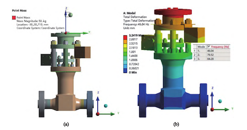
Figure 6. Three-dimensional geometric model and first-order mode shape of the valve
(a) Three-dimensional geometric model (b) First-order modal vibration mode shape
3.3 Seismic Performance Verification
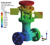
During seismic analysis, the worst-case operating conditions and most unfavorable load combinations were taken into account. The pressure-bearing performance of the valve components was evaluated by considering internal pressure under severe accident conditions, valve deadweight, seismic loads, and end loads. Finite element simulations were performed using ANSYS, with stress linearization applied to analyze high-risk regions of pressure-bearing components, such as the valve body, where stress levels were significant. The calculated stress and overall deformation results are presented in Figures 7(a) and 7(b).
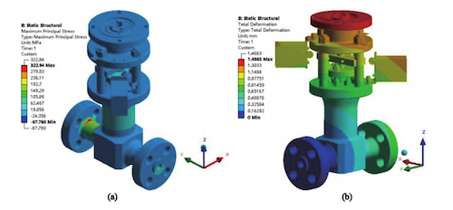
Figure 7: Stress and Deformation Results of the Complete Valve Assembly
(a) Stress Distribution (b) Total Deformation Cloud Diagram
Figure 7 shows that under the combined loading conditions, the valve exhibits a low overall stress level. The maximum equivalent (von Mises) stress of 322.94 MPa occurs on the outer surface of the test process flange. Under the combined design and seismic loads, the valve experiences no plastic deformation, exhibiting a maximum elastic deformation of approximately 1.47 mm. The maximum deformation of the pressure boundary, responsible for media flow, does not exceed 0.4 mm. Overall deformation is minimal, remains well within design limits, and satisfies the valve’s functional requirements. The stress distribution and stress linearization results for the critical sections of the valve body, the primary pressure-bearing component, are presented in Figure 8. The calculations confirm that the stress assessment results for the valve body are satisfactory, and its structural strength fully complies with the required standards. The valve body stress evaluation results are summarized in Table 3.
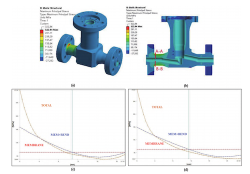
(a) Valve Body Stress Results (b) Valve Body Assessment Section (c) Stress Linearization Results for Section A–A (d) Stress Linearization Results for Section B–B
Figure 8 Valve body critical section stress assessment results
Table 3. Valve Body Stress Assessment Results
|
Assessment Path |
Stress Classification and Criteria |
Calculated Value (MPa) |
Allowable Value (MPa) |
Assessment Result |
|
A–A |
σm or σm+0.5σb≤1.5S |
90.9 |
113 |
Pass |
|
A–A |
σm or σm+0.5σb≤1.5S |
166.3 |
170 |
Pass |
|
B–B |
σm or σm+0.5σb≤1.5S |
90.1 |
113 |
Pass |
|
B–B |
σm or σm+0.5σb≤1.5S |
158.3 |
170 |
Pass |
Additional Component Stress Assessment
For other components, such as the valve stem, stress levels remained low, with the maximum total stress below the allowable limit of the material. Therefore, stress linearization was deemed unnecessary. Stress analyses were conducted on a prototype nuclear-grade electric bonnetless bellows globe valve under accident conditions. Stress classification and evaluation of key components—including the valve body, disc, stem, and column—were performed in accordance with the applicable criteria. The results verified that stresses in all critical regions remained within regulatory limits, thereby confirming the valve’s adequate structural integrity.
4. Manufacturing Plan
Comprehensive procurement specifications constitute the technical basis for part procurement, inspection, and associated processes. The raw material (blank) must conform to these specifications before machining commences. Machining shall be conducted in accordance with the designated process routing card, and each operation must successfully pass inspection prior to advancing to the subsequent step. Processing of parts requiring overlay welding shall adhere to the applicable operating specifications. Upon completion, a full-surface liquid penetrant inspection is required. In order to ensure weld quality and meet the performance requirements of fully welded products, process qualification for the applicable welds is performed in accordance with the valve’s design structure and the RCC-M Standard. As stipulated by the relevant standards, non-destructive testing (NDT), hardness testing, macroscopic examination, and additional evaluations are conducted on the test specimens. The results verify that all parameters comply with the specified criteria. The welding process is validated as both reasonable and effective, thereby ensuring superior weld quality. All components shall pass inspection and be marked with a qualified label before proceeding to the assembly stage. All threaded components, including valve stems and stem nuts, must be fully deburred to prevent galling or seizure during assembly. Components subject to sealing requirements shall undergo visual inspection and surface roughness assessment. Assembly shall commence only upon successful completion of these inspections. The assembly process shall be conducted in strict accordance with the process instruction documents and in compliance with the manufacturer’s internal specifications. Upon assembly completion, the valve shall be operated through two full open-close cycles to confirm smooth operation, with no sticking or abnormal noise observed.
Factory testing includes the following:
Shell strength test
Shell seal test
Disc strength test
Seat seal test
Seat gas seal test
Bellows hydrostatic test
Actuation test
5. Conclusion
This paper presents a bellows globe valve solution aimed at reducing valve leakage and facilitating rapid assembly and disassembly, specifically designed for application in nuclear power plant areas inaccessible to routine maintenance. This solution further minimizes the risk of valve leakage while significantly reducing maintenance time. Verification of flow characteristics, structural stiffness, and seismic performance confirms that the nuclear-grade electric bonnetless bellows globe valve possesses excellent rigidity (≥ 33 Hz), robust seismic resistance, and superior flow capacity (Cn ≥ 7.31, L/D ≤ 340). These performance metrics comply with the latest Hualong One nuclear power technology standards, ensuring the long-term and stable operation of valves in areas of nuclear power plants that are inaccessible for routine maintenance.
Send your message to this supplier
Related Articles from the Supplier
Related Articles from China Manufacturers


Related Products Mentioned in the Article
Supplier Website
Source: https://www.baltic-valve.com/nuclear-grade-bellows-globe-valves-for-hard-to-access-areas-in-nuclear-power-plants.html