FEA and Design Optimization of Cryogenic Globe Valves
Abstract: This study presents the structural optimization of a cryogenic globe valve for liquid helium and liquid hydrogen applications using epoxy fiberglass components, aiming to reduce heat leakage without compromising mechanical strength. Finite element analysis (FEA) is used to simulate the thermal and stress behavior of the valve before and after structural optimization. The analysis focuses on temperature and stress distribution in key components—such as the valve body, extended neck tube, valve stem, and epoxy fiberglass—under ultra-low-temperature conditions. The results reveal significant temperature gradients across the long neck tube, valve stem tube, and epoxy fiberglass sections. However, the optimized design significantly reduces thermal leakage while maintaining adequate pressure resistance and structural integrity to meet safety and performance standards.
1. Overview
With the rising demand for ultra-low-temperature systems—driven by the growing use of liquefied natural gas (LNG) and the storage and transportation of cryogenic fluids such as liquid helium, liquid hydrogen, and liquid oxygen—the application of cryogenic globe valves has become increasingly widespread. To ensure safe and reliable operation, effective thermal insulation and sealing performance are critical design requirements for cryogenic valves. Previous studies—such as the work by Li Kang et al.—used simulation tools to analyze thermal and mechanical behavior in a DN250 cryogenic globe valve, revealing excessive thermal stress concentrated in the extended neck tube. This thermal stress was identified as a key factor contributing to material deformation and reduced valve performance. Building on previous research, this study investigates a newly designed cryogenic globe valve, comparing its thermal and mechanical performance before and after structural optimization. Epoxy fiberglass, known for its low thermal conductivity and high mechanical strength, is incorporated into the design to improve both thermal insulation and structural performance. Through comparative finite element simulations, the study demonstrates that incorporating epoxy fiberglass components significantly increases the temperature at the stuffing box and ensures that stress levels in both the valve body and fiberglass sections remain within acceptable limits, complying with cryogenic valve design standards.
2. Modeling and Simplification
2.1 Creation of a Simplified Valve Model
Following industry guidelines for finite element analysis (FEA) of cryogenic valves, non-essential details were removed to reduce meshing time without compromising accuracy. The handwheel, bellows, and similar appendages were removed as they have a negligible impact on heat transfer and stress analysis results. Threaded holes in non-critical areas were suppressed for the same reason to streamline the model without compromising analysis accuracy. The outer vacuum jacket was omitted, and its insulating effect was represented by a default “vacuum insulation” boundary condition in the software. The resulting computational domain is shown in Figure 1 (Simplified Valve Model).

Figure 1 Simplified valve schematic diagram
2.2 Finite Element Model Setup
2.2.1 Material Definitions
Valve body and stem: ASTM A182 F316 stainless steel
Packing (filler): Graphite
Insulating spacer/tube: Epoxy–fiberglass composite (properties based on peer-reviewed test data)
Since the stem has minimal impact on the overall temperature and stress distribution, it is modeled using the same material properties as the valve body (F316 stainless steel). Thermal conductivity (λ) and linear expansion coefficient (α) data for stainless steel are sourced from the Mechanical Design Manual. Properties of the epoxy–fiberglass composite are listed in Table 1.
Table 1 Thermal conductivity and linear expansion coefficient of epoxy glass
|
Temperature (°C) |
Thermal Conductivity λ (W · m⁻¹ · K⁻¹) |
Linear Expansion Coefficient α (10⁻⁶ K⁻¹)* |
|
36.3 |
0.400 |
— |
|
–158.4 |
0.248 |
— |
|
–173.1 |
0.160 |
— |
|
–179.4 |
0.027 |
— |
Linear expansion data at cryogenic temperatures were unavailable in the referenced study and are therefore assumed to be temperature-independent in the model.
Additional Elastic Constants:
Epoxy–fiberglass: Young’s modulus = 5.5 GPa, Poisson’s ratio = 0.27
Stainless steel (F316): Young’s modulus = 195 GPa, Poisson’s ratio = 0.32
These values enable accurate coupling of thermal and structural fields in subsequent simulations, ensuring reliable predictions of heat leakage, deformation, and sealing performance for liquid helium and liquid hydrogen globe valves.
2.2.2 Boundary Condition Settings
(1) Thermal Load Conditions
The pipeline’s internal temperature is set to –263 °C. The valve body’s outer surface is considered insulated, with ambient heat transfer modeled via natural convection. A convection coefficient of 8 W/(m²·°C) is applied to surfaces exposed to air, with an ambient temperature of 22 °C.
(2) Mechanical Load Conditions
Thermal stress is derived from the simulated temperature field. Applied mechanical loads include:
Internal pressure: 3.1 MPa
Torsional moment: 480 kN·mm
Tensile load: 135 kN
The applied boundary conditions for both thermal and mechanical fields are illustrated in Figure 2 (Temperature and Mechanical Load Settings of the Valve Body).
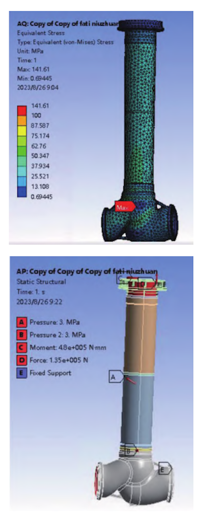
Figure 2 Temperature load setting and load setting for valve body force calculation
2.2.3 Mesh Generation
The mesh model is shown in Figure 3. Since the sealing pressure ratio is not the primary focus and stress differences between the open and closed valve positions are negligible, the open state was selected for simulation. The mesh is generated using a size control method to balance accuracy and computational efficiency.
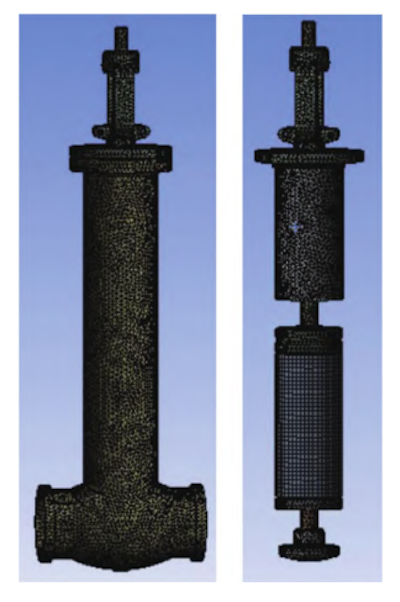
Figure 3: Mesh division
3. Simulation Results and Analysis
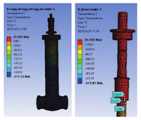
3.1 Comparison of Temperature Fields Before and After Valve Optimization at Ultra-Low Temperatures
Figure 4 illustrates the temperature distribution before optimization. The simulation reveals a significant temperature gradient among the extended neck tube, valve stem tube, and epoxy fiberglass section. The surface temperature at the stuffing box before optimization is 13.3 °C. The total heat leakage before optimization is 97.5 W, with the valve body accounting for 84.7 W, due to the high thermal conductivity of stainless steel. The valve stem contributes 4.8 W to the overall heat loss.

Figure 4: Temperature Field Before Optimization
Figure 5 shows the temperature distribution after optimization. A similar temperature gradient is observed among the long neck tube, valve stem tube, and epoxy fiberglass. However, the surface temperature at the stuffing box rises to 17.1 °C. This improvement is primarily attributed to the reduced thickness of the stainless steel outer layer, which shortens the heat conduction path.
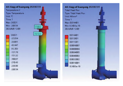
Figure 5: Temperature Field After Optimization
These results confirm that the lowest temperatures are found in valve components directly exposed to the cryogenic medium, especially the valve body. Both simulations reveal a consistent temperature gradient along the long neck and valve stem sections, emphasizing the critical role of structural design in thermal management.
In summary:
- The stuffing box surface temperature increased from 13.3 °C to 17.1 °C after optimization.
- Heat leakage through the stainless steel casing was significantly reduced.
- Using epoxy fiberglass-reinforced components reduces overall thermal conduction and increases local operating temperatures.
Therefore, incorporating epoxy fiberglass in valve design effectively reduces cryogenic heat leakage and raises stuffing box temperature, thereby enhancing thermal performance and operational safety in liquid hydrogen and liquid helium valve systems.
3.2 Stress Analysis of the Valve at Ultra-Low Temperature
3.2.1 Simulation Results for the Optimized Design
Figure 6 shows the displacement and equivalent stress contours for the optimized cryogenic globe valve. Since the temperature gradient extends along the pipeline’s longitudinal axis, thermal displacement is similarly concentrated in that direction. Mechanical stress is generally uniform, with peak stress occurring at the pipeline gap—a local singularity typical of geometric discontinuities. Excluding this singularity, the average stress in the valve body is 172.95 MPa, well within the material limits of ASTM F316 stainless steel.
3.2.2 Comparison and Discussion
Figure 7 compares the epoxy fiberglass–reinforced (FRP) sleeve under combined thermal and mechanical loading conditions:
|
Parameter |
Observation |
Relevance |
|
Thermal deformation |
Dominant, driven by the longitudinal temperature gradient; peak deflection ≈ 4 mm |
Reflects the valve’s ability to absorb differential contraction |
|
Mechanical stress |
Localized at fixed constraints (stress singularities) but < 200 MPa overall |
Confirms that epoxy FRP meets cryogenic stiffness requirements |
|
Young’s modulus assumption |
Modeled as temperature independent; in reality, modulus rises at cryogenic temperatures |
Leads to a slight over prediction of deformation, but error is minor |
These results confirm that the epoxy–fiberglass sleeve maintains structural integrity at –263 °C service conditions while effectively accommodating thermal displacement. The valve body’s stress profile, averaging 172.95 MPa, meets design criteria, demonstrating that the optimized liquid helium/liquid hydrogen globe valve can safely withstand both thermal and mechanical loads.
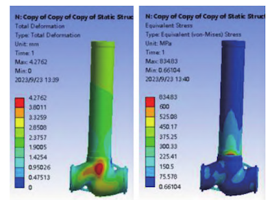
Figure 6: Displacement and stress distribution of the optimized valve under thermal and mechanical loads
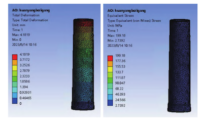
Figure 7: Deformation and stress distribution of the epoxy–FRP sleeve under identical loading conditions
4. Conclusion
This study employed comprehensive finite element analysis (FEA) to compare the thermal and mechanical performance of a cryogenic globe valve before and after structural optimization. The key findings are:
Epoxy–Fiberglass (FRP) Integration Reduces Heat Leakage
Replacing traditional metal sections with epoxy–fiberglass (FRP) significantly decreases heat transfer through the valve body and increases the stuffing box temperature. Simulation results confirm that epoxy FRP maintains sufficient strength at –263 °C, making the optimized design superior to conventional cryogenic valves.
Optimized Geometry Produces a Smoother Temperature Gradient
Although a distinct bottom-to-top temperature gradient remains in the long neck and valve stem tubes, the stuffing box temperature is significantly higher after optimization, improving seal reliability.
Main Heat Loss Pathways Are the Valve Body and Long Neck Tube
After adopting epoxy–FRP, overall heat leakage decreases sharply, significantly improving thermal efficiency in liquid helium and liquid hydrogen service.
Thermal Stress Is the Primary Driver of Valve Deformation
In the optimized valve, stress distribution is more uniform, and the epoxy–FRP sleeve safely withstands combined thermal and mechanical loads, meeting all cryogenic stiffness and strength requirements.
Send your message to this supplier
Related Articles from the Supplier
Related Articles from China Manufacturers
Related Products Mentioned in the Article
Supplier Website
Source: https://www.baltic-valve.com/fea-and-design-optimization-of-cryogenic-globe-valves.html