Improvement in Nuclear Grade Lift Check Valves (Part Two)
2.1.2 The width of the sealing surface
The sealing form of the valve seat and disc is a face seal. The face seal makes the contact surface of the valve spool and valve seat larger, which also leads to an increase in the sealing specific pressure; after the valve is opened and closed again, it is easy to leave medium in the sealing surface. The surface tension of the medium hinders the valve from opening again and increases the opening pressure of the valve. Therefore, the opening pressure of the valve can be reduced by reducing the width of the sealing surface.
2.2 The analysis of circulation capacity
Flow resistance coefficient and flow coefficient are often used for valves to describe their flow performance. The smaller the flow resistance coefficient and the higher the flow coefficient are, the better the flow performance of the valve becomes. Both of them are defined as the following:
Kv=2∆plpv2 (2)
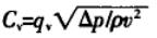 (3)
(3)
In the formula, C is the flow coefficient. K means the resistance coefficient. V is the velocity of the medium in the pipeline (m/s). ∆p stands for the pressure loss (Pa). P is the density of the medium (kg/m3). Qv is the volume flow (m3/h).
2.2.1 Pressure relief holes
When the force of the medium acting on the valve spool is greater than the sealing ratio pressure, the valve spool leaves the valve seat, and the medium flows into the upper cavity of the valve spool through the pressure relief hole. The valve spool is pushed and moves upward after overcoming the spring pressure and the friction force of the valve spool and valve body. In this article, the lift check valve has two pressure relief holes in the valve disc, which finally converge on a pressure relief groove to connect the upper cavity. This design has a certain effect of hindering the medium from entering the upper cavity, which reduces the flow rate in the medium pipeline, aggravates the generation of turbulence in the middle cavity, increases the pressure loss flowing through the valve, reduces the flow stability of the medium in the valve, and increases the flow resistance coefficient of the valve. It can be seen that more pressure relief holes can make the valve's performance better according to the analysis of formula (3). The absolute value of negative pressure generated is small, which can reduce the probability of cavitation, and make the fluid inside the flow channel more stable.
2.2.2 The stroke of the valve spool
Small spool stroke leads to small space in the valve cavity, large flow resistance, small medium flow rates, resulting in small flow rates of media in the pipeline, and great pressure loss ∆p flowing through the valve. Properly increasing the valve stroke can reduce the negative pressure area at the valve outlet, make the internal medium more stable. The flow coefficient is increased, and the flow resistance coefficient is reduced accordingly. Therefore, the valve stroke can be increased.
3. Measures
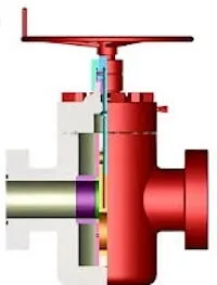
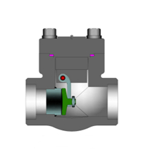
After discussing with the design institute and valve manufacturer based on the above analysis results, the valve manufacturer redesigned and provided a design drawing (Figure 2).

Figure 2 The improved valve
The sealing surface of the improved valve adopts the line sealing for the valve spool and valve seat, which reduces the width of the sealing surface and avoids the obstacle of medium tension in the opening process of the valve. The back pressure spring is canceled for the valve, and there is no need to overcome the spring resistance in the opening process of the valve spool, which reduces the sealing specific pressure of the valve. Increase the number of the pressure relief hole to 4 to make it easier for the medium to enter the upper cavity of the valve, which reduces the pressure loss of the valve, increases the flow rate of the medium in the valve, and is beneficial to increasing the valve's flow coefficient. Appropriately increase the opening stroke of the valve spool to make the valve obtain a larger valve cavity and an effective flow area of the outlet section, which is beneficial to increasing the flow rate of the medium in the valve, reducing the flow resistance, increasing the flow of the medium and high-speed area, making the pressure loss flowing through the valve reduced, the flow stability significantly improved, and the flow capacity of the valve improved.
4. Conclusion
Taking the check valve at the boric acid recirculation pump outlet of the safety injection system of Qinshan No. 2 Nuclear Power Plant as an example, suggestions for improvement of the nuclear grade lift check valve are proposed based on the aspects of valve states and flow capacity combined with structure characteristics of valves.
(1) The backpressure spring of the check valve and the width of the contact surface determine the sealing specific pressure. The spring pressure and the width of the contact surface should be appropriately reduced under the premise of ensuring the sealing specific pressure to reduce the opening pressure of the valve.
(2) The number of pressure relief holes and the stroke of the valve spool affect the flow rate of the medium in the valve and the pressure loss flowing through the valve. Increasing the number of pressure relief holes and stroke of the valve spool can reduce the flow resistance of the valve and improve the flow capacity of the valve.
The sealing form of the valve seat and disc is a face seal. The face seal makes the contact surface of the valve spool and valve seat larger, which also leads to an increase in the sealing specific pressure; after the valve is opened and closed again, it is easy to leave medium in the sealing surface. The surface tension of the medium hinders the valve from opening again and increases the opening pressure of the valve. Therefore, the opening pressure of the valve can be reduced by reducing the width of the sealing surface.
2.2 The analysis of circulation capacity
Flow resistance coefficient and flow coefficient are often used for valves to describe their flow performance. The smaller the flow resistance coefficient and the higher the flow coefficient are, the better the flow performance of the valve becomes. Both of them are defined as the following:
Kv=2∆plpv2 (2)
(3)In the formula, C is the flow coefficient. K means the resistance coefficient. V is the velocity of the medium in the pipeline (m/s). ∆p stands for the pressure loss (Pa). P is the density of the medium (kg/m3). Qv is the volume flow (m3/h).
2.2.1 Pressure relief holes
When the force of the medium acting on the valve spool is greater than the sealing ratio pressure, the valve spool leaves the valve seat, and the medium flows into the upper cavity of the valve spool through the pressure relief hole. The valve spool is pushed and moves upward after overcoming the spring pressure and the friction force of the valve spool and valve body. In this article, the lift check valve has two pressure relief holes in the valve disc, which finally converge on a pressure relief groove to connect the upper cavity. This design has a certain effect of hindering the medium from entering the upper cavity, which reduces the flow rate in the medium pipeline, aggravates the generation of turbulence in the middle cavity, increases the pressure loss flowing through the valve, reduces the flow stability of the medium in the valve, and increases the flow resistance coefficient of the valve. It can be seen that more pressure relief holes can make the valve's performance better according to the analysis of formula (3). The absolute value of negative pressure generated is small, which can reduce the probability of cavitation, and make the fluid inside the flow channel more stable.
2.2.2 The stroke of the valve spool
Small spool stroke leads to small space in the valve cavity, large flow resistance, small medium flow rates, resulting in small flow rates of media in the pipeline, and great pressure loss ∆p flowing through the valve. Properly increasing the valve stroke can reduce the negative pressure area at the valve outlet, make the internal medium more stable. The flow coefficient is increased, and the flow resistance coefficient is reduced accordingly. Therefore, the valve stroke can be increased.
3. Measures
After discussing with the design institute and valve manufacturer based on the above analysis results, the valve manufacturer redesigned and provided a design drawing (Figure 2).
Figure 2 The improved valve
The sealing surface of the improved valve adopts the line sealing for the valve spool and valve seat, which reduces the width of the sealing surface and avoids the obstacle of medium tension in the opening process of the valve. The back pressure spring is canceled for the valve, and there is no need to overcome the spring resistance in the opening process of the valve spool, which reduces the sealing specific pressure of the valve. Increase the number of the pressure relief hole to 4 to make it easier for the medium to enter the upper cavity of the valve, which reduces the pressure loss of the valve, increases the flow rate of the medium in the valve, and is beneficial to increasing the valve's flow coefficient. Appropriately increase the opening stroke of the valve spool to make the valve obtain a larger valve cavity and an effective flow area of the outlet section, which is beneficial to increasing the flow rate of the medium in the valve, reducing the flow resistance, increasing the flow of the medium and high-speed area, making the pressure loss flowing through the valve reduced, the flow stability significantly improved, and the flow capacity of the valve improved.
4. Conclusion
Taking the check valve at the boric acid recirculation pump outlet of the safety injection system of Qinshan No. 2 Nuclear Power Plant as an example, suggestions for improvement of the nuclear grade lift check valve are proposed based on the aspects of valve states and flow capacity combined with structure characteristics of valves.
(1) The backpressure spring of the check valve and the width of the contact surface determine the sealing specific pressure. The spring pressure and the width of the contact surface should be appropriately reduced under the premise of ensuring the sealing specific pressure to reduce the opening pressure of the valve.
(2) The number of pressure relief holes and the stroke of the valve spool affect the flow rate of the medium in the valve and the pressure loss flowing through the valve. Increasing the number of pressure relief holes and stroke of the valve spool can reduce the flow resistance of the valve and improve the flow capacity of the valve.
Send your message to this supplier
Related Articles from the Supplier

Related Articles from China Manufacturers
Improvement in Butterfly Check Valves
- Jul 13, 2022
Improvement in Butterfly Check Valves
- Jun 29, 2022


Related Products Mentioned in the Article
Supplier Website
Source: https://www.uvalve.cn/news/improvement-in-nuclear-grade-lift-check-valves-part-two.html