Fracture Analysis of Reheat Drain Pipe Elbow in Ultra-Supercritical Unit
This study investigates the cause of fracture in the reheat hot section drain pipe elbow of a 1000 MW ultra-supercritical thermal power unit on the B-side. A series of experimental analyses, including macroscopic morphology, metallographic structure, hardness, and mechanical property tests, were performed on the fractured elbow and surrounding areas. The drain pipe is constructed from P92 alloy steel, measuring 38.1 mm by 5 mm, with an operating temperature of 603°C and a working pressure of 4.79 MPa. Results reveal that repeated temperature fluctuations cause constrained thermal expansion and contraction in the pipe, leading to thermal stress cycles and fatigue damage at the elbow. This leads to the initiation of thermal fatigue cracks, while surface pits on the elbow’s outer wall act as stress concentrators, accelerating crack development. The measured hardness of the elbow exceeded the maximum limit specified by relevant standards, which reduced its resistance to deformation. During condensate discharge, load fluctuations and intermittent flow caused significant changes in flow velocity and vibration at the elbow, accelerating crack propagation and leading to eventual failure.
Introduction
With China’s rapid economic growth, energy demand—particularly for electricity—has surged, making it an indispensable resource for both industrial and societal development. Although renewable energy technologies are advancing, they have not yet reached sufficient maturity to fully replace thermal power generation, primarily due to technical limitations and environmental challenges. To meet growing electricity demand while improving resource efficiency and reducing environmental pollution, thermal power plants are increasingly adopting high-capacity, high-efficiency units, including supercritical and ultra-supercritical systems. In this context, the drain system, a vital auxiliary thermal subsystem, plays a crucial role in discharging condensate, minimizing working fluid loss, and preventing water hammer during power generation. However, inadequate maintenance and outdated management of drain systems have caused an increasing number of failures—such as leaks and ruptures—especially in high-parameter, large-capacity thermal power units. These problems significantly threaten the safety and reliability of thermal power generation systems, highlighting the urgent need for thorough analysis of component failures within the drain system.
Incident Overview and Initial Response
On June 22, 2022, a reheat steam leak was detected at the elbow of the reheat hot drain pipe on the B side of Unit 1, a 1,000 MW ultra-supercritical unit at a thermal power plant. The leak occurred near the elbow located just before the pressure-free water discharge valve (see Figure 1 for the burst location). Plant personnel promptly carried out emergency repairs by drilling and injecting adhesive to temporarily seal the leak. However, on June 29, the elbow ruptured at the same location. After an on-site inspection and verification, it was confirmed that the rupture originated from the previously repaired leak point. To identify the root cause of the failure, the damaged pipe section was removed and underwent detailed analysis, including macroscopic examination, metallographic study, hardness testing, and mechanical property evaluation.
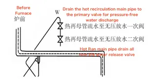
Figure 1. Location of the Reheat Hot Section Drain Pipe
1. Failure Analysis
1.1 Macroscopic Morphology Observation
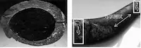
The fractured elbow section of the reheat hot drain pipe, shown in Figure 2(a), exhibits a crack-like rupture with minimal plastic deformation, indicating a brittle fracture. To determine the root cause of the failure, material samples were collected from multiple locations (see Figure 2(b)); sample No. 1 was taken adjacent to the fracture, while sample No. 2 was taken from a distant straight pipe section. Another specimen was collected from the straight pipe section, indicated by the white arrow in Figure 2(b), for mechanical property testing. Magnetic Particle Inspection (MPI) was conducted on the back arc surface of the elbow to detect potential subsurface defects. As shown in Figure 3(a), distinct magnetic indications confirmed the presence of clustered transverse cracks, with the longest crack measuring approximately 20 mm. To further evaluate internal damage, the elbow was longitudinally sectioned and underwent additional magnetic particle inspection (MPI). As shown in Figure 3(b), multiple magnetic indications appeared along the inner wall, revealing numerous transverse cracks and confirming that crack propagation extended through the elbow wall.
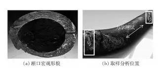
(a) Fracture macromorphology (b) Sampling and analysis position
Figure 2
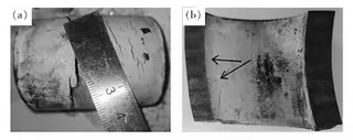
Figure 3 Cracks at the elbow
1.2 Physical and Chemical Testing
1.2.1 Mechanical Properties and Hardness Testing
As described in Section 1.1, a room-temperature tensile test was performed on the straight section of the reheat drain pipe using a universal mechanical testing machine. The test results are summarized in Table 1, showing that the tensile strength, yield strength (specified non-proportional extension), and elongation of the straight pipe specimen fully comply with relevant industry standards. Due to structural constraints, tensile testing on the elbow was not feasible; therefore, a portable AIS 3000 Compact mechanical property tester was employed to assess the room-temperature mechanical properties of cross-sectional samples from Sample No. 1 (elbow section) and Sample No. 2 (straight pipe section). These tests were performed following the "Technical Specification for Instrumented Indentation Testing of Mechanical Properties of Metallic Materials in Power Plants" (DL/T 2220-2021), with the results summarized in Table 2. Although both samples meet the standard requirements for tensile strength and yield strength (specified non-proportional extension strength), the values measured at the elbow section are significantly higher than those at the straight pipe section. This increase in strength may reduce the bend’s deformation resistance, raising concerns about material embrittlement and the potential for crack propagation under fluctuating operating conditions.
Table 1 Room Temperature Tensile Test Results Using Universal Mechanical Testing Machine
|
Item |
Material |
Tensile Strength Rm (MPa) |
Yield Strength Rp0.2 (MPa) |
Elongation (%) |
|
Standard Requirement (ASME) |
P92 |
≥ 620 |
≥ 440 |
≥ 17 |
|
Straight Pipe Mechanical Specimen 1 |
P92 |
690 |
450 |
21 |
|
Straight Pipe Mechanical Specimen 2 |
P92 |
736 |
497 |
18 |
Note: The measured wall thickness of the straight pipe section used in mechanical testing is 5.8 mm, making the minimum required elongation 17%.
Table 2 Room Temperature Mechanical Properties Measured by Portable Universal Mechanical Properties Tester
|
Item |
Material |
Tensile Strength Rm (MPa) |
Yield Strength Rp0.2 (MPa) |
|
Specimen No. 1 (Elbow section) |
P92 |
1,230 |
948 |
|
Specimen No. 2 (Straight pipe) |
P92 |
744 |
588 |
Note: Mechanical properties were evaluated using the AIS 3000 Compact portable tester in accordance with DL/T 2220-2021, Technical Specification for Instrumented Indentation Testing of Mechanical Properties of Metallic Materials in Power Plants.
The results indicate that while both samples meet standard mechanical strength requirements, the elbow section shows significantly higher tensile and yield strength values compared to the straight pipe section. Such elevated strength is often linked to excessive hardness, which can reduce ductility and increase the likelihood of crack initiation and propagation under thermal and mechanical stress.
The hardness of Sample No. 1 and Sample No. 2 was measured using a microhardness tester. The results are shown in Table 3.
Table 3 Microhardness Test Results
|
Sample ID |
Location |
Hardness (HB) |
|
Sample No. 1 |
Elbow Section |
> 250 |
|
Sample No. 2 |
Straight Pipe |
Within 180–250 |
According to the "Technical Supervision Regulations for Metals in Thermal Power Plants" (DL/T 438-2016), the acceptable hardness range for P92 pipe fittings is 180–250 HB. Test results confirm that Sample No. 2 meets the standard requirements, whereas Sample No. 1 significantly exceeds the upper hardness limit, suggesting potential embrittlement and reduced ductility at the elbow.
1.2.2 Microstructure Analysis
To further investigate the cracks near the fracture of the drain pipe elbow, the microstructure of Specimen No. 1 was examined using an optical microscope. As shown in Figure 4, multiple cracks were observed in the sample, extending through both the inner and outer walls. Oxidation around the crack edges suggests prolonged exposure to high temperatures. Further inspection revealed multiple corrosion pits on the outer wall of the elbow (Figure 4c), with the deepest pit measuring approximately 595.25 μm. Crack propagation was clearly observed originating from the pit site (Figure 4d). The metallographic structure of Specimen No. 1 is shown in Figure 5. The base metal exhibits a tempered martensitic structure, which appears relatively stable. This suggests that the material retains favorable high-temperature mechanical properties, despite the presence of cracking and localized damage.
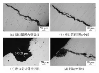
(a) Cracks on the inner wall near the fracture (b) Middle section of the crack near the fracture (c) Pitting on the outer wall near the fracture (d) Crack propagation at the pit location
Figure 4: Microscopic Morphology of Specimen No. 1
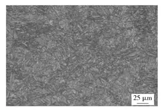
Figure 5: Metallographic Structure of Specimen No. 1
Summary and Conclusion
The root cause of the elbow fracture in the drain pipe was identified as thermal fatigue, which gradually diminished the pipe’s fatigue strength. Thermal fatigue cracks initiate at multiple sites and, as they propagate and merge, the material’s structural integrity progressively deteriorates. Additionally, corrosion pits on the outer wall acted as vulnerable initiation sites for crack propagation. This situation was further aggravated by excessive hardness in the elbow section—measured above the upper limit specified by relevant standards—which compromised the material’s ductility and resistance to deformation. As a result, thermal fatigue cracks originated at the inner surface and propagated outward, ultimately causing fracture at the elbow’s weakest section (C911).
2. Analysis of Fracture Causes and Recommendations
2.1 Analysis of Fracture Causes
During startup or normal operation of the unit, the drain valve is opened to discharge condensate from the drain tank into the condenser. The steam trap’s operation is regulated by the condensate level: it opens when the level rises and closes when the level falls. This control method makes it difficult to fully discharge all condensate, causing residual water to remain inside the steam trap. As the unit continues to operate, reheated steam gradually warms the steam trap from above. Because of the condensate inside, a significant temperature gradient develops between the upper and lower sections of the steam trap. This temperature gradient induces thermal stress both between the inner and outer walls and between the upper and lower sections.Over time, repeated heating and cooling cycles cause localized thermal fatigue in the metal, resulting in the formation of cracks in areas where fatigue strength is most severely reduced. Additionally, several pits were observed on the outer wall of the elbow. These surface defects act as stress concentrators, making them likely sites for crack initiation and propagation. Hardness testing showed that the elbow section exceeded the industry standard’s upper limit, substantially reducing the material’s ductility and resistance to deformation, especially at location G213. The intermittent discharge of condensate causes fluctuations in pressure, flow velocity, and fluid density within the drain pipe. These dynamic conditions are further intensified during load changes—particularly during peak load regulation—subjecting the elbow area to cyclic mechanical and thermal stresses. The combined effects of thermal fatigue, material hardening, and mechanical vibration ultimately lead to fracture at the elbow.
2.2 Recommendations
To prevent future failures and ensure the long-term safety and reliability of the reheated hot section drain pipe, the following measures are recommended:
Enhance monitoring of operating conditions to reduce excessive temperature gradients and mechanical vibrations, thereby minimizing thermal fatigue and structural damage.
Increase the frequency of non-destructive testing (NDT) on drain pipes to identify early signs of defects or cracks, enabling timely repair or replacement of affected components.
Strengthen quality control during component manufacturing to eliminate production defects that could compromise mechanical performance and reduce service life. Install suitable vibration dampening systems on the drain line to reduce dynamic stresses and inhibit the propagation of fatigue cracks.
3. Conclusion
The fracture of the elbow in the reheated hot section drain pipe was primarily caused by cyclic thermal loading from condensate on the pipe wall, which led to the initiation and propagation of thermal fatigue cracks. The metallographic structure at the elbow consists of stable tempered martensite, indicating that the material maintains good high-temperature mechanical properties. However, numerous pits were found on the outer surface of the elbow, acting as initiation sites for crack formation. Additionally, the elbow’s hardness exceeded the upper limit specified by industry standards, which diminished its resistance to deformation. Intermittent condensate discharge, coupled with load fluctuations during peak regulation, resulted in significant pipe vibrations. When the vibration frequency of the condensate matched the pipe’s natural frequency, resonance occurred, accelerating crack propagation and ultimately causing the elbow to fail.
Send your message to this supplier
Related Articles from the Supplier
Related Articles from China Manufacturers

Causes of Fracture of SS304 Check Valves (Part One)
- Sep 10, 2022

Causes of Fracture of SS 304 Check Valves (Part Two)
- Sep 23, 2022
Related Products Mentioned in the Article
Supplier Website
Source: https://www.landeepipefitting.com/fracture-analysis-of-reheat-drain-pipe-elbow-in-ultra-supercritical-unit.html