Flange Sealing Technology and Installation Method for Hydrogenation Units
Abstract: Hydrogenation reactors are critical components in hydroprocessing units, and the sealing of their top flanges involves high technical requirements and operational complexity. Drawing on lessons from a previous flange seal failure during the initial start-up of a 3 million t/a diesel hydrogenation unit—caused by inadequate maintenance preparation and sealing surface compression failure—this study identifies the root causes and optimizes the flange installation and sealing process. Key improvements include accurate bolt preload torque calculations, comprehensive inspection and repair of flange sealing grooves, bolts, and gaskets, as well as precise grinding, alignment verification, and controlled bolt tightening procedures. These enhanced procedures were rigorously implemented on similar hydrogenation reactors, resulting in reliable flange sealing performance and valuable operational experience for future maintenance and installation. The reactor’s top flange seal, which uses an octagonal metal ring gasket, is engineered to withstand extreme conditions—including 8.0 MPa pressure, 399°C temperature, and highly corrosive hydrogen and hydrogen sulfide environments. Made from 2.25Cr-1Mo alloy, the reactor’s hot-wall plate welded structure demands a high-integrity flange seal to ensure safe startup and long-term reliable operation. As shown in Figure 1, the octagonal metal gasket is seated in a trapezoidal ring groove on the flange surface. When the flange bolts are tightened, axial compression induces plastic deformation of the gasket, creating an initial pressure-tight seal. Under operating pressure, the octagonal gasket expands radially and presses firmly against the inclined surfaces of the trapezoidal groove, forming a reinforced, self-tightening seal that is critical for high-pressure hydrogen service.
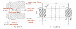
(a) Head Cover Sealing Configuration (b) Octagonal Gasket Structure
Figure 1. Reactor Flange Sealing Diagram
The hydrogenation unit was originally commissioned in 2011. During initial operation, leakage occurred at the reactor head cover flange. Inspection identified key issues including stress concentration on the sealing surface, poor sealing surface fit, and improper bolt tightening procedures. A disassembly and reinstallation strategy was implemented to resolve the issue. Upon disassembly, it became clear that the sealing structure was highly specialized and the operating conditions were complex. Due to a lack of prior experience, completing the flange sealing required over 20 days of trial and error, including multiple disassembly and reassembly attempts, which significantly delayed the unit’s start-up. In August 2016, as part of an upgrade and capacity expansion of the hydrogenation unit, a new reactor of identical specifications was installed. To prevent recurrence of previous issues and ensure smooth commissioning, the flange sealing technology for the hydrogenation reactor was thoroughly researched and optimized beforehand, addressing key technical challenges prior to installation.
1. Analysis of the Causes of Head Cover Flange Seal Leakage
Fluid leakage at the reactor head cover flange generally occurs in two ways: leakage through the gasket itself or leakage along the compression surface between the flange and gasket. The reactor flange’s non-standard octagonal gasket features a radial self-tightening design that effectively eliminates the risk of internal gasket leakage. Therefore, the primary focus shifts to leakage along the flange’s compression surface, with common causes including:
Inadequate Bolt Preload – Insufficient flange bolt preload fails to meet sealing requirements, resulting in gasket sealing pressure that is either too high or too low to ensure effective sealing.
Improper Bolt Tightening Sequence – Not following the correct tightening procedure results in uneven compression across the flange sealing surface, compromising the seal integrity.
Poor Contact Surface Quality – The large size of the equipment can lead to suboptimal machining accuracy on the non-standard octagonal gasket contact surface, adversely affecting sealing performance.
Surface Damage from Corrosion or Disassembly – Corrosion and repeated disassembly can damage the sealing surface, creating potential leakage paths.
Defects in the Flange Groove or Head Cover – Structural flaws in the flange sealing groove or head cover can cause misalignment, resulting in seal failure.
Bolt Surface Contamination – Large flange bolts, if not properly cleaned and maintained during installation, can accumulate rust and debris on the threads, compromising tightening uniformity and flange sealing integrity.
By identifying these factors, the sealing reliability of reactor head cover flanges can be significantly enhanced, reducing the risk of leakage during high-pressure hydrogenation operations.
2. Research on Comprehensive Sealing Solutions
2.1 Bolt Preload Control
Due to unavoidable deviations in flatness and parallelism of the reactor head cover flange sealing surfaces, achieving reliable sealing under normal operating conditions requires precise control of the gasket preload pressure ratio. To ensure a reliable seal, the applied preload on the octagonal metal gasket must exceed the operating pressure ratio. This preload pressure is generated by the bolt load. As the bolt load increases, the gasket experiences elastic deformation, which improves contact at the sealing surface. However, the bolt load must not exceed the yield strength of the gasket material. If plastic deformation occurs, the gasket loses its elastic recovery ability, reducing its effectiveness in responding to pressure and temperature fluctuations. A reduced sealing pressure ratio—especially when it falls below the operating pressure ratio—can result in severe flange leakage. Therefore, the required bolt preload must be calculated based on actual operating conditions. The bolt tightening torque, Me, is determined using the following equation:

Variable Definitions
Fe: Minimum tightening force of the narrow-faced flange gasket (N)
b: Effective sealing width of the gasket (mm)
D: Diameter of the center circle for the gasket tightening force (mm)
m: Gasket factor (dimensionless)
p: Design pressure of the reactor (MPa)
Lc: Radial distance from the bolt center to the point of action of Fe (mm)
Based on the reactor design drawings and applicable national standards—GB 150.1–150.4-2011 (Pressure Vessels), NB/T 47041-2014 (Tower Vessels), and JB 4732-1995 (Steel Pressure Vessel – Analytical Design Standard)—the following design parameters were determined:
Substituted Values:
b = 5.38 mm
D = 1050 mm
m = 6.50
p = 9.24 MPa
Lc = 135 mm
Substituting these values into Equations (1) and (2), the required total bolt tightening torque is calculated as:
Me = 287,640.685 N·m
With 24 flange bolts used on the reactor head cover, the average minimum preload torque per bolt is:
M = Me / 24 = 11,985 N·m
However, multiple tightening trials demonstrated that the theoretically calculated minimum torque alone was insufficient to ensure a reliable seal. Further analysis revealed that additional torque is required to compensate for factors such as:
Thread deformation during tightening
Residual dirt on contact surfaces
Loss of tension after releasing the nut from the tightening device
Based on prior installation and maintenance experience, the final bolt tightening torque was set at 1.1 times the theoretical minimum, resulting in a hydraulic wrench torque of:
13,184 N·m per bolt
2.2 Flange Sealing Groove
Before reinstalling the disassembled reactor head cover flange, thoroughly clean the flange surface and sealing groove using a suitable cleaning agent. The sealing groove is then polished with 800-grit sandpaper to achieve a smooth finish. Following surface preparation, a dye penetrant inspection (color contrast method) is conducted to detect any defects. Inspection results confirmed that the original reactor flange sealing groove met all quality standards. This phrasing emphasizes verification and uses keywords like inspection results, flange sealing groove, and quality standards. However, a minor surface crack was detected in the sealing groove of the new reactor. To address this, a portable flange facing machine was deployed on-site to repair both the sealing groove and the adjacent flange surface (Figure 2). Post-repair testing confirmed that the sealing groove met all technical requirements, and the repair quality was satisfactory.
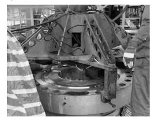
Figure 2. On-Site Repair of Flange Sealing Groove in Hydrogenation Reactor
2.3 Gaskets and Bolts
Before installation, the sealing surfaces of the octagonal metal gaskets for both reactor flange connections underwent a thorough visual inspection. The gaskets were required to be free from scratches, dents, cracks, or any other surface defects, with surface roughness not exceeding 1.6 μm. A random Rockwell hardness test was conducted on four gasket samples to verify compliance with HG/T 20633-2009, the standard for "Metallic Ring Gaskets for Steel Pipe Flanges (Class Series). According to the standard, the octagonal gasket’s hardness must be 30–40 HB lower than that of the flange sealing surface material, with uniform hardness maintained throughout the entire gasket. Inspection results confirmed that the octagonal gaskets for both reactor flanges fully complied with all specified quality and performance requirements. The newly installed hydrogenation reactor was equipped with flange connection bolts supplied by the manufacturer, featuring standard threads conforming to GB/T 196-2003 "General Purpose Metric Screw Threads." Bolts removed from the original reactor were sorted by specification, soaked in diesel fuel for cleaning, and gently brushed with a wire brush to remove surface rust. The original bolts and nuts were reassembled according to their matching numbers and sequentially sent for inspection; once approved, they were carefully stored for reuse. Due to the heavy weight and large size of the bolts and nuts, extra care was exercised during disassembly, cleaning, and transportation to prevent thread damage and ensure sealing reliability upon reinstallation.
2.4 Flange Grooves
Before installation, it is essential to verify the fit between the octagonal metal gasket and the flange sealing groove. To ensure optimal sealing performance, the groove surface should be precisely processed using an abrasive compound. This task should be carried out by trained professionals. Abrasive material is applied to the sealing surface inside the flange ring groove, which is then ground using a specialized flange groove grinding tool.
After grinding the flange sealing groove for approximately five minutes, inspect the contact line between the flange groove and the octagonal gasket (see Figure 3). The inspection process includes the following steps:
- Apply a thin, even layer of red lead powder over the sealing surface of the octagonal gasket.
- Insert the gasket into the flange groove and rotate it by 45 degrees.
- Remove the gasket and inspect the contact line carefully, ensuring it is continuous and free of any gaps or interruptions.
- If any discontinuities are detected, repeat the grinding and inspection steps until the contact line meets the required quality standards.

Figure 3. On-site Inspection of Hydrogenation Reactor Flange Groove Contact Surface Using Red Lead Method
2.5 Tightening
Once the gasket, bolts, and flange groove fit have been thoroughly inspected and confirmed to meet specifications, the hydrogenation reactor head cover can be reinstalled by following these steps:
Gasket Installation: Carefully place the clean, qualified octagonal metal gasket into the flange sealing groove, ensuring it lies flat without any tilting, warping, or misalignment.
Thread Lubrication: Apply a sufficient amount of high-temperature anti-seize lubricant to the bolt threads, then turn the nut back and forth at least two full rotations to ensure smooth threading.
Nut-Flange Lubrication: This keeps important keywords like molybdenum disulfide (MoS₂) grease, contact surface, reduce friction, and tightening for SEO while improving flow.
Using the original hydrogenation reactor as a reference, a hydraulic torque wrench was employed to tighten the flange bolts in a cross-pattern sequence, ensuring even pressure distribution across the gasket. The tightening was performed in four stages, following the specified torque values:
Tighten to 50% of the final torque
Tighten to 75% of the final torque
Tighten to 100% of the final torque (first pass)
Tighten to 100% of the final torque (second pass for final verification)
After each tightening pass, the flange gap at each marked point was measured and recorded to ensure uniform compression across the flange. Final measurements were compared with those recorded before disassembly and found to be consistent, confirming correct reassembly. For the newly added hydrogenation reactor, a bolt tensioner was used to tighten the flange bolts, following the same cross-tightening sequence and procedure as the original unit, ensuring uniform stress distribution and reliable sealing performance.
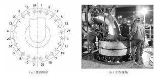
Figure 4. Tightening Sequence and Work Site for Hydrogenation Reactor Head Cover
(a) Bolt Tightening Sequence (b) On-Site Installation Operation
3. Conclusion
The hydrogenation reactor is a critical component of the hydrogenation unit, and the reliability of its flange sealing directly affects the safe and stable operation of the entire system. During the initial commissioning of the 3 million t/a diesel hydrogenation unit, flange leakage occurred at the reactor head cover due to limited experience in large-scale, high-pressure flange inspection and maintenance. Key issues included stress concentration on the sealing surface, poor gasket-to-groove fit, and improper bolt tightening techniques. These issues caused significant delays, increased labor and material costs, and disrupted the normal startup of the unit. To address these challenges and prevent recurrence, comprehensive sealing control measures were systematically developed, refined, and implemented during the installation of newly added hydrogenation reactor flanges of the same specifications in the 2016 modification and upgrade project. These measures included optimized bolt preload calculations, precise flange groove preparation, thorough gasket quality inspections, and a standardized tightening sequence using hydraulic tools. As a result, the flange sealing of both reactor head covers was successfully completed in a single attempt, requiring only two days. After commissioning, the hydrogenation unit started smoothly and has since operated reliably and normally. To date, the 3 million t/a diesel hydrogenation unit has operated continuously for one year without any flange sealing failures or abnormalities in the reactor head cover flanges.
Send your message to this supplier
Related Articles from the Supplier


Related Articles from China Manufacturers


Industrial valve and pipe installation instructions
- Oct 13, 2019

Precautions For Installation And Use Of Ball Valves
- Dec 14, 2024
.jpg)
Installation Technology of Plant Walls
- Jan 24, 2018
Related Products Mentioned in the Article


XIAMEN LANDEE INDUSTRIES CO., LTD.
- https://www.landee.cn/
- Address: NO. 321 JIAHE ROAD, XIAMEN, P.R.CHINA 361012
- Phone: 86-592-5204188
- Business Type: Trading, Manufacturer,
Supplier Website
Source: https://www.landeeflange.com/flange-sealing-technology-and-installation-method-for-hydrogenation-units.html