ANSYS Analysis for Anchor Flange Structural Optimization
Abstract
Anchor flanges are critical components of oil and gas pipeline systems, ensuring the protection of both pipelines and station equipment. Currently, no standards exist for anchor flange structural calculations, and widely used designs present certain local structural deficiencies. Using a specific oil pipeline as a case study, this research employed a gasketless flange model to determine the structural dimensions of the anchor flange. Numerical simulations in ANSYS were conducted to identify stress concentration zones and optimize the design. The results indicate that although the initial dimensions obtained from the gasketless flange model were reasonable, stress concentrations developed at the flange neck. Redesigning the flange neck into a two-stage smooth transition structure effectively eliminated these concentrations and significantly improved stress distribution across the flange cross-section. These findings offer practical guidance for the structural design of anchor flanges in future applications.
Introduction
Anchor flanges are essential components in large-diameter, high-pressure, long-distance gas and oil pipeline systems. They are welded to the main pipeline and anchored with cement piers, which may be partially or fully buried underground. Typically installed at pipeline entry and exit points, anchor flanges prevent excessive displacement resulting from combined forces such as the pipeline’s weight, internal pressure, temperature gradients, and changes in direction or alignment. Their function is to secure the pipeline, limit axial displacement, and protect both surface pipelines and station equipment. Due to their large diameters (200–1200 mm), high internal pressures (6–12 MPa), wide application range (pipelines spanning more than ten provinces), harsh operating conditions (complex geology, variable climates and temperatures, corrosion, and vibration), and strict safety requirements (crossing densely populated areas such as cities, rural communities, schools, and hospitals), anchor flanges must demonstrate extremely high operational reliability. However, no specific standards currently exist—either domestically or internationally—for the design, manufacture, inspection, or acceptance of anchor flanges. In practice, design requirements are generally based on ASME Section VIII (GB/T 150), ASME B31.4 (GB 50253), and ASME B31.8 (GB 50251) standards, supplemented by engineering experience. The structural dimensions of the ports are determined in accordance with ASME B31.4 (GB 50253) and ASME B31.8 (GB 50251). A typical anchor flange is an axisymmetric ring forging with a flange, featuring symmetrical necks on both sides that are welded to the ends of the pipeline. Once secured to the anchor pier, this design effectively restrains pipeline movement and safeguards station equipment. However, theoretical calculations often have limitations, which can result in unreasonable structural dimensions in critical areas, localized stress concentrations, and potential safety risks. Using the design of a high-pressure, large-diameter anchor flange for an oil pipeline project as a case study, this paper applies finite element comparative analysis to optimize the anchor flange structure.
1. Structural Design
Design Assumptions
Since the portion embedded in the anchor pier includes the anchor flange and sections of the pipeline (or inner sleeve) on both sides, it is assumed that the pipeline embedded within the anchor pier does not undergo deformation or other failure modes and can effectively transmit axial thrust. The primary design conditions for the anchor flange of the specific oil pipeline are summarized in Table 1.
Table 1. Anchor Flange Design Conditions
|
Parameter |
Specification |
|
Design Standards and Specifications |
ASME Section VIII, Div. 1; ASME B31.4 |
|
Design Factor |
0.6 |
|
Anchor Flange Specification |
DN700 |
|
Pipeline Design Standard |
ASME B31.4 |
|
Connecting Pipeline Dimensions |
711 mm × 15.88 mm (OD × WT) |
|
Connecting Pipeline Material |
API 5L GR X-65, PSL-2, LSAW |
|
Design Pressure |
9.5 MPa |
|
Installation Temperature |
15 °C |
|
Operating Temperature |
50–70 °C |
|
Design Temperature |
85 °C |
|
Corrosion Allowance |
0 mm |
|
Installation Method |
Buried |
|
Design Axial Thrust (internal pressure, temperature differential, and other loads) |
5,300,000 N |
|
Concrete Grade |
C25 |
|
Concrete Compressive Strength (design value) |
11.9 MPa |
|
Allowable Stress for Flange |
270 MPa |
The anchor flange should be manufactured as a solid forging with excellent thermal processing characteristics. The forged material must possess the required microstructure, strength, and toughness, while also demonstrating excellent weldability to ensure the integrity of the weld between the anchor flange and the mating pipe. Because the anchor flange is subjected to complex loading conditions, high-strength or strength-matched materials are required to prevent external loads from concentrating strain at the weld between the anchor flange and the pipe. For this design, the anchor flange is made of ASTM A694 F65. The structural configuration and stress analysis are shown in Figure 1. Based on the existing anchor flange structure (Figure 1), the following assumptions were made: the anchor flange is considered to consist of a gasketless long-neck butt-weld flange and a welded neck (Figure 2). It is further assumed that the girth weld is fully penetrated, even though, in practice, no such weld is present.
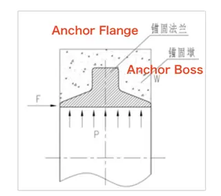
Figure 1. Structural Form and Force Analysis Schematic
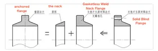
Figure 2. Anchor Flange Structure Decomposition Schematic
It is known that the forces acting on two bolted flanges are symmetrical, whereas the forces on an anchor flange are asymmetrical, which supports the assumption described above. Additionally, while bolted flanges transmit stress through the bolt cross-sections, an anchor flange transmits thrust from the anchor pier through the flange face on the neck side of the gasketless long-neck butt-weld flange. Therefore, when calculating the anchor flange based on the gasketless long-neck butt-weld flange, the bolt diameter is taken as the width of the flange face, and the bolt center spacing is assumed to be equal to one nominal bolt diameter. Because the anchor pier must withstand the thrust transmitted by the anchor flange, it should be arranged symmetrically to prevent localized compression. To prevent pier failure, the minimum required flange bearing area should be calculated based on the compressive strength of the anchor pier. The final structural dimensions of the anchor flange can then be determined using the design procedure for gasketless welded long-neck flanges.
The pressure per unit area of the anchor pier is given by:
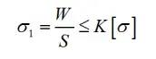
Where:
σ — Pressure per unit area of the anchor pier, MPa
W— Axial thrust borne by the anchor pier, equal to the total axial thrust FNF_NFN
S — Axial thrust bearing area of the anchor pier, mm²
K — Safety factor (range 0–0.8)
[σ]— Design value of concrete compressive strength, MPa
Based on this calculation, the structural dimensions of the anchor flange are determined, as illustrated in Figure 3.
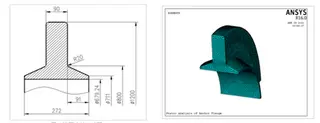
Figure 3 Dimension drawing of anchor flange
Figure 4 Grid division model of anchor flange
2. Finite Element Analysis
In the finite element analysis of the anchor flange, the element type used was Solid187 (10-node tetrahedral), and the mesh is shown in Figure 4. Constraints were applied to the flange face, while internal pressure and axial thrust were imposed as loading conditions. The simulation results for axial stress, hoop stress, radial stress, and von Mises equivalent stress (Figures 5(a)–5(d)) were 215 MPa, 168 MPa, 359 MPa, and 338 MPa, respectively. Both the radial stress and the von Mises equivalent stress exceeded the allowable limit of 270 MPa, indicating potential failure at the flange neck.
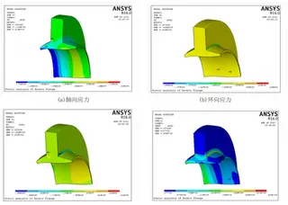
(a) Axial stress (b) Hoop stress
(c) Radial stress (d) von Mises equivalent stress
Figure 5. Stress distribution of the anchor flange
The optimized anchor flange dimensions are shown in Figure 6, with the corresponding finite element mesh presented in Figure 7. After applying the same boundary conditions and loads, the resulting axial stress, hoop stress, radial stress, and von Mises equivalent stress (Figures 8(a)–8(d)) were 194 MPa, 125 MPa, 120 MPa, and 242 MPa, respectively, all below the allowable limit of 270 MPa, thereby satisfying the design requirements. The total strain distribution is shown in Figure 9, with a maximum strain of 1.427 mm, which is well below 0.03D (21.33 mm), confirming that the design meets the requirements.
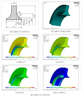
Figure 6. Optimized anchor flange dimensions
Figure 7. Optimized anchor flange mesh model
Figure 8. Stress distribution of optimized anchor flange
(a) Axial stress (b) Hoop stress
(c) Radial stress (d) Mises equivalent stress
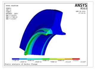
Figure 9. Total strain distribution
3. Conclusion
In conclusion, the gasketless flange calculation model provides a reliable basis for the preliminary sizing of the anchor flange structure. ANSYS numerical simulations identified stress concentrations at the flange neck. Introducing a two-stage smooth transition at the flange neck effectively reduced these stress concentrations and improved the structural performance of the anchor flange.
Send your message to this supplier
Related Articles from the Supplier

Related Articles from China Manufacturers
Related Products Mentioned in the Article
Supplier Website
Source: https://www.landeeflange.com/ansys-analysis-for-anchor-flange-structural-optimization.html