Key Technologies and Design Considerations for Hydrogen Pipeline Ball Valves
Abstract: With the rapid expansion of long-distance hydrogen pipelines in China, the application of pipeline ball valves is expected to become increasingly widespread. However, China currently lacks comprehensive standards for the design, manufacturing, and application of high-pressure hydrogen pipeline ball valves. This gap has led to numerous challenges in product development and research, limiting the wider adoption of these valves. This paper analyzes the properties of hydrogen as a medium and its impact on materials, while addressing key technical challenges in material selection, structural design, manufacturing, and testing of valves for long-distance hydrogen pipelines. The findings offer a valuable reference for the design, development, and application of ball valves in hydrogen pipeline systems.
Introduction
Hydrogen energy, as a key secondary clean energy source, has garnered worldwide attention. Although China is a leading hydrogen producer, the hydrogen energy sector faces a significant supply-demand imbalance. Currently, long-haul tube trailers remain the primary means of transporting hydrogen over long distances in China; however, this method is costly and inefficient, driving up end-use hydrogen prices and severely restricting the growth of related industrial chains. In contrast, hydrogen pipelines allow for large-scale, long-distance transmission while maintaining strong economic efficiency, positioning them as one of the most promising technologies for establishing a networked and reliable hydrogen supply system. High-pressure, large-diameter, and long-distance pipeline technologies represent the future direction of hydrogen transportation development. Hydrogen pipelines, especially long-distance ones, operate under unique conditions shaped by geographic factors, operating parameters, media properties, and strict safety requirements. Fully welded ball valves, as critical components in hydrogen pipeline systems, are widely used due to their simple design, full-bore configuration, and low flow resistance. As a result, valves for long-distance hydrogen pipelines must meet much higher performance standards than general-purpose valves, requiring enhanced reliability, superior sealing, and greater structural strength to ensure safe and stable operation. This paper presents the key technical considerations for ball valves in high-pressure pure hydrogen transmission pipelines, offering a reference framework for the design and development of pure hydrogen pipeline ball valves in China.
1. Material Selection
The pipeline transports hydrogen, a flammable and explosive gas classified as a hazardous chemical. Under standard conditions, hydrogen is colorless, odorless, non-toxic, and non-corrosive, but it has extremely high permeability, with a density of 0.089 kg/m³, making it lighter than air. Hydrogen ignites easily, and its flame is nearly invisible, making combustion difficult to detect, with a hydrogen–oxygen mixture burning at temperatures of 2100–2500 °C. The explosive limits of hydrogen range from 4.2% to 74% in air and from 5.0% to 94.3% in oxygen. Hydrogen also exhibits strong reducing properties, making it widely used as a protective gas during the annealing of cold-rolled stainless steel and carbon steel coils in steel plants. Hydrogen’s effects on metallic materials primarily manifest as hydrogen embrittlement, hydrogen corrosion, and hydrogen-induced bulging. Hydrogen embrittlement occurs when hydrogen dissolved in steel recombines into hydrogen molecules, creating localized stress concentrations that exceed the material’s strength limit. This leads to severe lattice distortion and the formation of microcracks within the steel, and once hydrogen embrittlement occurs, the damage is irreversible. Therefore, materials with low susceptibility to hydrogen embrittlement, such as nickel- and molybdenum-alloyed steels, should be selected, and measures should be taken to minimize hydrogen permeation into the metal. Coatings with low hydrogen diffusivity and solubility can also be applied. Generally, hydrogen tends to remain in steel after electroplating with Zn, Cd, Sn, or Pb, whereas coatings like Cu, Mo, Al, Ag, Au, and W exhibit low hydrogen diffusivity and solubility, reducing hydrogen permeation. Under high temperature and pressure, hydrogen can diffuse into metals and chemically react with certain elements, causing hydrogen corrosion. In these conditions, hydrogen-resistant steels should be selected to ensure material integrity and pipeline safety. Suitable hydrogen-resistant steels include 16MnR, 15CrMoR, 14Cr1MoR, 2Cr–0.5Mo, 2.25Cr–1Mo, and 3Cr–1Mo–0.25V. The chromium and molybdenum in these alloys promote the formation of stable carbides, minimizing the likelihood of hydrogen reacting with carbon. Hydrogen atoms can also diffuse into voids or cavities within the steel, where they recombine to form hydrogen molecules. Since these molecules cannot escape, this generates extremely high internal pressure within the metal. This phenomenon, called hydrogen bulging, can lead to swelling or even cracking of the steel surface. When the medium contains toxic substances such as hydrogen sulfide, arsenic compounds, cyanides, or phosphorus ions, these agents hinder hydrogen release and significantly increase the risk of hydrogen bulging. To reduce the risk of hydrogen bulging, killed steels with minimal internal cavities are commonly selected. Alternatively, materials with low hydrogen permeability, such as austenitic stainless steels, can be chosen, or protective linings like nickel or fiberglass can be applied.
Although hydrogen corrosion can be theoretically classified into the three types mentioned above, in practice, these mechanisms almost always occur simultaneously. Therefore, equipment operating in hydrogen-corrosive environments must give careful consideration to material selection. Common hydrogen-resistant materials typically include austenitic stainless steels, precipitation-hardened austenitic alloys, low-alloy steels, aluminum alloys, and copper alloys. According to the national standard GB 50177, "Design Code for Hydrogen Stations," hydrogen pipelines should use ball valves and gate valves. When the operating pressure exceeds 2.5 MPa, the valve body, stem, and sealing surfaces of hydrogen-service valves must be constructed entirely from stainless steel. However, in practical applications, material selection must account not only for hydrogen compatibility but also for the weldability of the pipeline steel during valve installation. As a general rule, the valve material should closely match the pipeline material. In long-distance hydrogen pipeline projects, low-grade line pipes, such as API SPEC 5L PSL2 X52 and lower, are commonly employed. Therefore, although stainless steel offers excellent hydrogen compatibility, carbon steel is still frequently used for valve bodies because it is easier to weld to the pipeline and is more cost-effective. For pure hydrogen transmission pipelines, however, higher operating pressures and stronger materials significantly exacerbate hydrogen embrittlement. In addition, welding defects and residual stresses can markedly raise the risk of hydrogen-induced steel failures, necessitating careful engineering and design precautions.
2. Ball Valve Structure
Pipeline ball valves have developed alongside advances in pipeline engineering. Globally, hydrogen pipeline construction started earlier, with relevant technical standards including ASME B31.12-2019 “Hydrogen Piping and Pipelines,” Europe’s CGA G-5.6 “Hydrogen Piping Systems,” and Asia’s AIGA 033/14 “Hydrogen Piping Systems.” In China, current hydrogen pipeline standards include GB 50177 “Design Code for Hydrogen Stations,” GB 4962 “Safety Technical Regulations for Hydrogen Use,” and GB 34542 “Hydrogen Storage and Transportation Systems.” However, there is currently no dedicated standard system for long-distance hydrogen pipelines, and no national standard specifically governs ball valves used in pure hydrogen transmission pipelines. Currently, the most widely applied standards are API 6D, issued by the American Petroleum Institute, and the international standard ISO 14313. The operating environment and conditions of hydrogen pipeline ball valves demand exceptionally high performance, with the primary technical requirements including:
(1) Strength and Toughness
Ball valves must withstand both steady and transient internal pressures of the hydrogen medium, in addition to axial forces induced by temperature variations. Additionally, external loads resulting from climatic conditions and terrain—such as the need for low-temperature impact toughness in permafrost regions—must also be taken into account. For fully welded ball valves, the fracture toughness of both the weld seam and the heat-affected zone is critical, making overall reliability the primary requirement for hydrogen pipeline ball valves.
(2) Zero-leakage sealing
As isolation components in pipelines, ball valves must provide superior sealing performance, achieving Class Zero sealing to ensure complete shut-off of the downstream pipeline. The impact of medium cleanliness on achieving a Class Zero seal must be considered; consequently, combined sealing structures are often employed to maintain reliable and consistent sealing performance.
(3) Automatic cavity pressure relief
Ball valves must prevent the medium from becoming trapped within the valve cavity, and the potential for cavity pressurization should be addressed during the initial design phase. Valves must feature an automatic pressure-relief mechanism, with the maximum relief pressure not exceeding 1.33 times the valve’s rated pressure.
(4) Fire Safety and Static Electricity Protection
Pipeline ball valve designs must include safeguards for fire scenarios, ensuring that both external and internal leakage remain within the limits specified by API 607. For hydrogen applications, special attention must be given to static electricity accumulation, and the valve should incorporate a conductive design to prevent electrostatic discharge.
(5) Drainage and Blowdown Capability
The valve must allow impurities and condensates in the valve cavity to be safely discharged through an external drainage system. The valve should also support online seal testing via the drainage system, enabling verification of sealing performance without removing the valve from operation.
(6) Position indication
Regardless of the actuation method, the valve must feature a clear and intuitive position indicator to show whether it is open or closed.
(7) Drive train requirements
The transmission chain must be designed so that its rated torque is at least twice the maximum operating torque of the ball valve, ensuring safe and reliable operation under all conditions.
(8) Corrosion protection
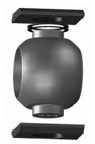
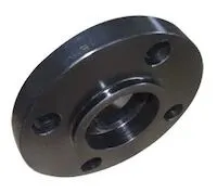
The valve should feature a fully welded body design, with the pipeline grounded for cathodic protection and the exterior surfaces treated with anti-corrosion coatings to prevent both general and stress corrosion caused by environmental factors. Pipeline ball valve bodies are typically classified into two types: fully welded spherical bodies and fully welded cylindrical bodies. Valve bodies should be made from forged materials and undergo non-destructive testing to verify structural integrity and ensure reliable performance. Figure 1 shows the fully welded spherical valve body design by Cameron (USA). Manufacturers using similar fully welded spherical designs include BORSIG and Schuck (Germany), Larsen & Toubro (USA), KITZ, TIX, and TUBOTA (Japan), and Tyazhpromarmatura (Russia). Figure 2 depicts the fully welded cylindrical valve body design by Grove (Italy). Manufacturers of cylindrical welded valve bodies include Nuovo Pignone, PCC, PERAR, B.F.E., PIBIVIESSE, and FCT (Italy), PBV (USA), and ČEZARM (Czech Republic).
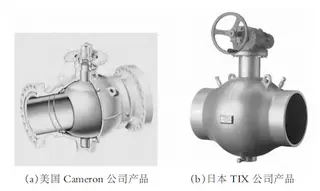
Figure 1 Fully welded pipeline ball valves
(a) Cameron, USA (b) TIX, Japan
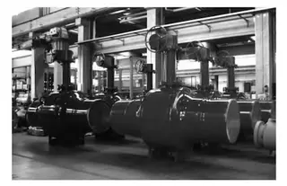
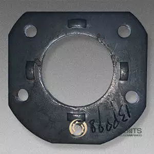
Figure 2 Fully welded cylindrical pipeline ball valve
Sealing between the valve seat and the ball typically uses a combined structure. A metal-to-metal hard seal protects the surfaces from scratches caused by solid particles, while a soft rubber seal against the ball ensures a Class Zero shutoff. For special operating conditions, an emergency sealant injection system is incorporated to provide temporary sealing. The rubber sealing ring is designed with either a cylindrical embedded profile or a hook-type combined profile to prevent blowout and ensure reliable sealing. Where installation space permits, a mechanical clamping structure can also be employed to secure the valve seat sealing ring, further enhancing seal reliability. To enhance sealing performance and wear resistance, the ball and valve seat are typically surface-hardened using methods such as nitriding, chrome plating, or hard-alloy overlay welding. These surface treatments enhance hardness and scratch resistance, as shown in Figure 3. The valve seat features an elastic design to provide the necessary initial sealing force, typically using compression springs, leaf springs, or butterfly springs. Depending on pipeline process requirements, the inlet and outlet seats may be configured as either single-piston-effect (SPE) self-relieving seats or double-piston-effect (DPE) dual-sealing seats. In the single-piston-effect design, the inlet-side seat automatically relieves pressure to the downstream pipeline whenever the cavity pressure exceeds the downstream pressure; this is the standard configuration. In the double-piston-effect design, the valve cavity relieves pressure only when it exceeds 1.33 times the pressure corresponding to the valve’s pressure rating, venting to the external environment. A safety valve is therefore required. This configuration is optional. The two designs are shown in Figures 4 and 5.
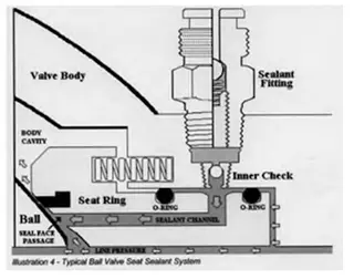
Figure 3 Grease-Injection Sealing Mechanism
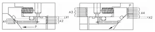
Figure 4 Single-Piston-Effect Seat—Schematic
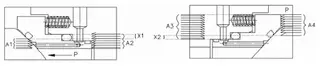
Figure 5 Double-Piston-Effect Seat—Schematic
The ball used in large-diameter pipeline ball valves adopts a fixed-ball, floating-seat design. The ball is supported at the top and bottom by bearings or support plates, which transfer the load generated by the medium to the supporting structure. For large-diameter, high-pressure hydrogen ball valves, the contact pressure on the supports must be carefully verified during the design stage to ensure it does not exceed the allowable limit. Using low-friction bearings or support structures effectively reduces the operating torque of the ball valve. Two structural approaches are commonly used for the support shaft. In the first approach, upper and lower journals are machined directly on the ball, and these journals are supported by upper and lower support plates equipped with stainless steel bushings lined with PTFE. The length of the support shaft is proportional to the journal diameter. In the second approach, the ball is machined with an internal bore and supported on the valve body by upper and lower support shafts. In the first design, the ball valve develops higher operating torque because the journal is short and relatively thick. In the second design, the upper support shaft also serves as the valve stem, transmitting torque and therefore being subjected to combined loading. Torque transmission between the stem and the ball can be accomplished either through a keyed connection or via a welded interface on the ball, as illustrated in Figure 6.
The valve stem primarily transmits the torque needed for valve closure and must include a sealing arrangement (Figure 6: ball and support-plate structure) to prevent external leakage. Additionally, the stem must incorporate an anti-blowout design to prevent ejection under internal pressure. It requires strength verification, including evaluation of torsional, shear, and compressive stresses at all critical cross-sections. Stem sealing can be accomplished with a two-stage O-ring or packing seal, complemented by fire-safe graphite packing and an emergency external sealant injection system. Anti-static devices must be installed at both the stem–ball and stem–body interfaces to prevent the buildup of static electricity. Additionally, a non-metallic gasket can be fitted at the flange of the blowout-proof structure to reduce friction, as illustrated in Figure 7.
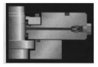
Figure 7 Double Stem Seal and Emergency Stem-Injection Structure
Control of pipeline ball valves is typically conducted remotely from a central control room, located far from the valve site. Therefore, valves must support remote automatic operation and allow emergency shutdown in situations such as fire. Actuator selection depends on site requirements, with options including manual, pneumatic, electric, electro-hydraulic, and pneumatic-hydraulic types. Electro-hydraulic actuators, capable of both local and remote control, are widely employed. Within the actuation chain, the connection between the actuator and the ball valve is the weakest mechanical link and requires strength verification, simulation analysis, and the implementation of anti-rotation mechanisms.
3. Ball Valve Manufacturing
The manufacturing process of ball valves directly influences their quality, sealing performance, and operating torque. In China, valve balls are typically manufactured using turning, but this method often yields insufficient machining accuracy and suboptimal roundness. These problems are especially pronounced in large-diameter balls, where meeting design specifications is challenging. Using milling, grinding, or CNC lathes with compensation capabilities can markedly enhance the precision of the balls. For welded ball valves, the welding process must manage challenges including the prediction and control of temperature fields, axial and radial deformations, and residual stresses. To address these challenges, appropriate welding methods should be selected, welding procedures and parameters optimized, specialized automated welding equipment and fixtures developed, and welding process qualification conducted. In cases where post-weld heat treatment is not feasible, a technical assessment must be conducted to ensure structural integrity.
4. Ball Valve Testing
Comprehensive performance testing is essential to verify the reliability of ball valves. Standard type tests typically include high-pressure tests, low-pressure tests, and fire-safety tests. Furthermore, many international manufacturers perform extensive reliability assessments, including external load bending tests, tensile and compression tests under external loads, air-blow tests, foreign-object blow-through and wear tests, emergency grease-injection sealing tests, load-bearing tests, seismic tests, long-term immersion tests, endurance tests, and electrostatic discharge tests.
5. Conclusion
The paper examines the critical technical aspects of hydrogen pipeline ball valves throughout their entire product lifecycle. It describes hydrogen-induced material degradation mechanisms, offers recommendations for selecting materials suitable for hydrogen service, details the special requirements for pipeline ball valves, and presents design strategies for key components. It further identifies critical challenges in ball valve manufacturing and testing, providing an initial exploration of development prospects for these products. For valves used in pure hydrogen pipelines, key near-term priorities include selecting appropriate materials and processes, investigating failure modes, and conducting comprehensive reliability assessments.
Send your message to this supplier
Related Articles from the Supplier
Related Articles from China Manufacturers
Key Technologies for Simulation Software of Stamping
- May 11, 2016


Key Points of Installating Blasting Machine
- Jan 05, 2016

Key Points for Transforming of Fiber Optic Industry
- Dec 17, 2015
Related Products Mentioned in the Article
balticvalve
- http://www.baltic-valve.com/
- Address: 厦门市思明区新景海韵园225号602室
- Phone: 0592-8266140
- Business Type: Trading,
Supplier Website
Source: https://www.baltic-valve.com/key-technologies-and-design-considerations-for-hydrogen-pipeline-ball-valves.html