Frequent Oil Pump Start-Stop in Ball Valve Systems at Jurong Pumped Storage Power Station
Abstract
The ball valve system at Jurong Pumped Storage Power Station is equipped with two screw-type oil pumps. During the commissioning of Unit 2, the oil pumps exhibited frequent start–stop cycles while the ball valve was open, with the minimum interval between starts reduced to just 16 minutes. The pumps stopped automatically upon reaching the preset stop pressure, and this abnormal behavior did not occur when the ball valve was closed. Through a systematic investigation of nine aspects—including the ball valve system’s hydraulic control circuit and the servo actuator piston chamber—the root cause was determined to be internal leakage in the hydraulic directional valve of the servo actuator’s opening circuit. This leakage allowed hydraulic oil to flow back to the return tank, causing a continuous pressure drop in the pressure oil tank and consequently triggering frequent start–stop cycles of the oil pumps. The analysis and corrective measures presented in this paper may serve as a reference for addressing similar issues in comparable systems.
Introduction
The Jurong Pumped Storage Power Station, located in Jiangsu Province (hereinafter referred to as Jurong Power Station), comprises six pump-turbine generator units, each with a rated capacity of 225 MW. The complete unit—including the inlet valve, turbine, and generator—was manufactured by Harbin Electric Machinery Co., Ltd. Each unit has a rated speed of 250 r/min and a rated head of 175 m. The inlet valve is a ball valve, model QF257-WY-340. Unit 2 began full-unit commissioning on October 16, 2024, and successfully completed a 15-day trial operation on December 14, 2024. The ball valve system primarily consists of the ball valve body, upstream connecting pipe, expansion joint, ball valve hydraulic operating device, and ball valve control system. The ball valve body comprises the valve body, valve stem, servo connector, servo connector hydraulic lock, bypass pipe, working seal, and maintenance seal. The ball valve hydraulic operating device primarily comprises a pressure oil tank, oil pumps, valve assemblies, and a return oil tank. The oil pumps transfer hydraulic oil from the return tank to the pressure oil tank. When the pressure in the pressure oil tank drops below 6.1 MPa, one oil pump is automatically started. When the pressure rises above 6.3 MPa, the oil pump stops. The hydraulic oil consumers include the ball valve relay, working seal, maintenance seal, hydraulic lock, and the working needle valve on the bypass pipe. Any abnormality in hydraulic oil consumption or malfunction of the oil pump can cause frequent start–stop cycles, adversely affecting the pumps’ service life and operational reliability.
1. Fault Description
On November 16, 2024, Unit 1 underwent no-load thermal stability testing and load thermal stability testing. During these tests, frequent start–stop operation of the oil pumps was observed when the ball valve was in the open position. On November 16, 2024, Unit 1 underwent no-load and load thermal stability tests. During these tests, the oil pumps exhibited frequent start–stop cycles while the ball valve was open. The start–stop interval data for the oil pumps are summarized in Table 1. During unit start-up, the governor system requires hydraulic oil pressure to regulate the guide vane openings for load adjustment. In contrast, the ball valve system normally does not require continuous oil pressure once the ball valve is fully open. However, comparing the oil pump operating intervals with the ball valve open and closed revealed a significant difference: the start–stop interval decreased from 11 hours and 45 minutes (ball valve closed) to just 16 minutes (ball valve open). This abnormal shortening of the start–stop interval indicates a fault in the ball valve hydraulic oil pressure system, leading to continuous pressure loss.
Table 1 Start–Stop Intervals of the Ball Valve Oil Pumps
|
Ball Valve Status |
Start Time |
End Time |
Operating Duration |
Number of Starts |
Average Start–Stop Interval |
|
Open |
Nov. 16, 15:01 |
Nov. 16, 20:48 |
5 h 47 min |
21 |
16 min |
|
Closed |
Nov. 15, 17:05 |
Nov. 16, 04:50 |
11 h 45 min |
1 |
11 h 45 min |
2. Cause Analysis
2.1 Structure of the Ball Valve Relay Body (Cause 1)
As shown in Figure 1, the relay cylinder and piston rod are made of forged steel. The piston is sealed with a single PTFE composite piston ring, and the piston rod is chrome-plated to provide a smooth surface and enhanced wear resistance. In addition, guide bands are installed on both the piston and the front cylinder head to prevent lateral loads on the seal and to ensure smooth and stable piston movement. The operating oil is supplied from the ball valve hydraulic system. The relay is equipped with an adjustable buffer device to ensure that the inlet ball valve moves at a reduced speed near the end of its full stroke, thereby preventing mechanical impact. Two pressure pipelines, designated as pressure lines A and B, are arranged at the outlet of the pressure oil tank. Pressure line A is directly connected to the closing chamber of the servo actuator, ensuring that this chamber remains continuously pressurized. Pressure line B connects to the opening chamber of the servo actuator through the ball valve control valve assembly. During ball valve opening, pressurized oil is supplied to both the opening and closing chambers of the servo actuator. The difference in effective piston areas between the two chambers generates an upward resultant force, driving the servo actuator and opening the ball valve. During ball valve closing, the control valve assembly cuts off pressure line B. The opening chamber of the servo actuator connects to the return oil tank, while the closing chamber remains connected to pressure line A. The combined hydraulic forces drive the servo actuator downward, closing the ball valve. Continuously pressurizing the closing chamber ensures reliable, fail-safe closure of the ball valve under abnormal operating conditions. The key difference between the ball valve opening and closing processes lies in the switching position of the control valve assembly for pressure line B.
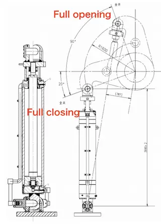
Figure 1. Structure of the Ball Valve Servo Actuator and Locking Mechanism
2.2 Hydraulic Control Circuit of the Ball Valve System
2.2.1 Relay Hydraulic Control Circuit (Cause 2)
The relay hydraulic control circuit consists of seven control valves:
One position-switching valve: provides hydraulic interlocking between the ball valve’s open state and the working seal disengagement state.
Three solenoid valves: one for ball valve opening and closing, and two for fail-safe (power-loss) shutoff.
Two hydraulic valves: one for mechanical overspeed protection and one for controlling the position of the hydraulic directional valve.
One hydraulic directional valve: controls the opening and closing of the relay’s opening chamber.
2.2.2 Working Seal Hydraulic Control Circuit (Cause 3)
The working seal hydraulic control circuit comprises four control valves:
One hydraulic interlocking valve: allows engagement of the working and maintenance seals only when the ball valve is fully closed.
One solenoid valve: controls the hydraulic valve responsible for engaging and disengaging the working seal.
One hydraulic valve: regulates the working seal’s oil–water control.
One oil–water control valve: switches the working seal water circuit.
2.2.3 Maintenance Seal Hydraulic Control Circuit (Cause 4)
The maintenance seal hydraulic control circuit also consists of four control valves:
One hydraulic interlocking valve: ensures that the maintenance seal engages only when both the ball valve and working seal are fully closed.
One manual directional valve: controls the hydraulic valve responsible for engaging and disengaging the maintenance seal.
One hydraulic valve: regulates the oil–water control for the maintenance seal;
One oil–water control valve: switches the maintenance seal water circuit.
2.2.4 Relay Locking Hydraulic Control Circuit (Cause 5)
The relay locking hydraulic control circuit consists of a single solenoid valve, which controls the locking and unlocking of the relay mechanism.
2.2.5 Bypass Needle Valve Hydraulic Control Circuit (Cause 6)
The bypass needle valve hydraulic control circuit consists of a single solenoid valve, which controls the opening and closing of the bypass needle valve. In each hydraulic circuit valve group, the return line is connected to the return oil tank. Any internal leakage within a valve group allows pressurized oil to flow back to the return tank, causing a drop in pressure in the pressure oil tank and triggering frequent start-up of the oil pump.
Note: The troubleshooting scope described above does not include the manually operated, normally open isolation valve.
2.3 Locking and Bypass Needle Valve Structural Analysis (Cause 7)
The locking valve and bypass needle valve use piston-type structures similar to the ball valve servo actuator, with a sealing element installed on the piston. If the piston seal fails to maintain tightness, internal leakage can occur, allowing pressurized oil to bypass the piston. This leakage causes a drop in the pressure oil tank, triggering automatic start-up of the oil pump.
2.4 Pressure Oil Tank Structural Analysis (Cause 8)
The pressure oil tank assembly includes air supply and exhaust pipes, as well as oil drain piping. If the exhaust line is improperly connected or the drain valve is not fully closed, oil or compressed air may escape from the system. This leakage reduces pressure in the pressure oil tank, triggering frequent start-up of the oil pump.
2.5 Oil Pump Supply Circuit Analysis (Cause 9)
The oil pump is connected to the pressure oil tank via pipeline B. A combination valve assembly at the pump outlet integrates a check valve, safety relief, and unloading functions. When the pump outlet pressure reaches the pressure oil tank pressure, the check valve opens, allowing the pump to deliver oil from the return oil tank to the pressure oil tank. After the pump stops, the check valve prevents reverse flow. If the check valve fails or does not seat properly, pressurized oil from the pressure oil tank can flow back to the return oil tank through the pump, causing a pressure drop and triggering automatic start-up of the oil pump. All nine potential causes described above can lead to pressure loss in the pressure oil tank, triggering frequent start–stop operation of the oil pump.
3. Troubleshooting and Corrective Actions
3.1 Preliminary Cause Investigation
On the afternoon of November 16, frequent start–stop cycles of the oil pump were observed when the ball valve was in the open position. This abnormal behavior ceased once the ball valve was closed. During the tests conducted on the same day, the bypass needle valve, maintenance seal, pressure oil tank drain valve, and exhaust valve were not actuated. Therefore, faults associated with these components would not exhibit the observed behavior whereby the pressure drop ceased after the ball valve was closed. Similarly, failures associated with the locking relay piston chamber and the oil pump outlet check valve are inconsistent with the observed behavior, as no frequent oil pump start-ups occurred when the ball valve was closed. Based on the above observations, Causes 4, 6, 7, 8, and 9 were provisionally ruled out.
3.2 Investigation of Internal Leakage in the Working Seal and Locking Hydraulic Circuits
Following the tests conducted on November 16, the working seal valve assembly and the locking hydraulic valve assembly were each maintained in the disengaged state for 15 minutes under static conditions. During this period, no measurable pressure drop was detected in the pressure oil tank. These results confirm the absence of internal leakage in the working seal and locking hydraulic circuits. Accordingly, Causes 3 and 5 were excluded.
3.3 Investigation of Suspected Relay Unit Collapse
When the fault occurred, some technicians initially attributed the abnormal condition to internal collapse of the relay unit, which would allow hydraulic oil to leak from the opening chamber to the closing chamber. However, the ball valve relay unit at the Jurong Pumped Storage Power Station is designed differently from those used at other power stations. To ensure reliable valve closure under abnormal or emergency conditions, the closing chamber of the relay unit is continuously connected to the pressure oil tank rather than to the return oil tank. Consequently, even if internal leakage were to occur between the opening and closing chambers, it would not cause a pressure drop in the pressure oil tank. In addition, during the electromechanical installation phase, all ball valve relay units underwent a pressure-withstand test at 1.5 times the design pressure at the manufacturing facility, witnessed by the construction supervision unit, and no abnormalities were observed. Based on the above analysis, relay unit collapse (Cause 1) was ruled out.
3.4 Analysis of Hydraulic Valve Group in the Relay Unit
Following the preceding elimination process, the most likely remaining cause was internal leakage in one or more of the seven control valves within the relay unit hydraulic control circuit. Given the rapid pressure drop in the pressure oil tank and the fact that the hydraulic directional valve has the largest internal flow passages and structural dimensions, this valve was identified as the primary focus of the investigation. After shutdown on the afternoon of November 17, the ball valve was operated independently, and the manually operated isolation valve on the hydraulic directional valve’s return oil line was closed. Observations showed that after one minute, the pressure drop in the pressure oil tank was only 0.01 MPa. Once the isolation valve was reopened, the pressure drop returned to the fault condition. After 15 minutes, the pressure dropped by 0.2 MPa, triggering another oil pump start. The detailed test results are summarized in Table 2.
Table 2 Oil Pump Start–Stop Behavior under Different Return Line Conditions
|
Operating Condition |
Start Time |
End Time |
Duration |
Pressure Drop |
Oil Pump Starts |
Start–Stop Interval |
|
Ball valve open, return line isolated |
14:30 |
14:47 |
17 min |
0.01 MPa |
0 |
— |
|
Ball valve open, return line connected |
14:47 |
15:02 |
15 min |
0.20 MPa |
1 |
15 min |
3.5 Determination of the Root Cause
Based on the foregoing analysis, the root cause of the frequent oil pump start–stop behavior was determined to be internal leakage in the hydraulic directional valve of the ball valve relay hydraulic control circuit (Cause 2). Specifically, internal oil leakage was detected from port P to port T of the hydraulic directional valve. The functional schematic of the valve in its closed position is shown in Figure 2. After replacing the hydraulic directional valve, the ball valve was reopened for observation. After 4 hours and 50 minutes of operation, the pressure drop in the pressure oil tank was only 0.1 MPa, with no abnormal pressure loss observed. During this period, the oil pump remained inactive, indicating that the fault had been successfully resolved. The corresponding operational data are summarized in Table 3.
A comparison of Tables 1 and 3 under ball valve closed conditions shows that:
- Before the replacement, the pressure in the oil tank dropped by 0.2 MPa over 11 hours and 45 minutes.
- After the replacement, the pressure drop was reduced to 0.1 MPa over 16 hours and 45 minutes.
This comparison further indicates that, before the replacement, the hydraulic directional valve experienced minor yet persistent internal leakage from port P to port T, even with the ball valve closed.
Table 3 Oil Pump Start–Stop Behavior after Directional Valve Replacement
|
Operating Condition |
Start Time |
End Time |
Duration |
Pressure Oil Tank Pressure Drop |
Oil Pump Starts |
Start–Stop Interval |
|
Ball valve open |
24th 16:04 |
24th 20:54 |
4 h 50 min |
0.1 MPa |
0 |
— |
|
Ball valve closed |
23rd 18:25 |
24th 11:10 |
16 h 45 min |
0.1 MPa |
0 |
— |
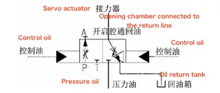
Figure 2 Functional Diagram of Hydraulic Directional Valve (Closed Position)
These findings indicate that the hydraulic directional valve was not subjected to sufficiently rigorous internal leakage testing during manufacturing. Consequently, the valve experienced short-term performance degradation after commissioning, which negatively impacted oil pump operation. The manufacturer suggested replacing the valve stem seal on site; however, this approach was deemed impractical, as the construction site lacks the necessary pressure testing facilities to verify internal leakage performance. High-precision hydraulic valve assemblies must undergo thorough leakage testing at the rated test pressure to ensure long-term operational reliability. Accordingly, the defective valves were returned to the manufacturer for rework and retesting.
4. Conclusions
This study provides a systematic analysis of the frequent start–stop behavior of oil pumps in the ball valve hydraulic system at Jurong Pumped Storage Power Station. By taking into account both the structural features of the ball valve and the operational logic of the hydraulic control system, the fault was efficiently identified and resolved. The troubleshooting approach proved clear, logical, and effective, greatly enhancing the efficiency and accuracy of fault detection and resolution. The findings and methodology presented in this paper offer valuable guidance for diagnosing and resolving similar frequent start–stop issues of oil pumps in ball valve systems at other pumped storage and conventional hydropower plants.
Send your message to this supplier
Related Articles from the Supplier
Related Articles from China Manufacturers
The Fatigue Strength Design of Frequent Switch Valve
- Aug 01, 2016
Related Products Mentioned in the Article
Supplier Website
Source: https://www.baltic-valve.com/frequent-oil-pump-start-stop-in-ball-valve-systems-at-jurong-pumped-storage-power-station.html