Fault Analysis and Diagnosis of Pneumatic Globe Valves in Nuclear Power Plants
Abstract
Small-bore pneumatic globe valves in nuclear power plants are subject to strict technical and safety requirements, making them a critical focus in the localization of nuclear power equipment. During operation, these valves are prone to failures, including valve disc cracking and leakage at the diaphragm or vent holes, which can cause valve malfunction or leakage and compromise system safety. This paper examines the common operational failures of a typical small-bore pneumatic globe valve and proposes standardized equipment protection procedures alongside fault diagnosis methods. The findings offer valuable guidance for the installation, commissioning, operation, and maintenance of CPR1000 nuclear power units and serve as a practical reference for valve manufacturers.
1. Overview
Valves are devices that control the flow of media—such as water, steam, oil, and gas—within pipelines, performing essential functions including isolation, flow and pressure regulation, direction control, and protection of pipelines and equipment. Due to their reliable performance and effective isolation capabilities in systems with stringent nuclear safety requirements, pneumatic globe valves are extensively used in CPR1000 nuclear power plants across systems such as RCP, RCV, REN, RIS, RPE, RAZ, SIR, APG, ETY, and VVP 133t, with each unit containing over 140 valves. Failures of these valves can seriously compromise the performance of associated systems and threaten the safe and stable operation of the nuclear power unit. According to partial statistics, in nuclear power systems—and the process industry more broadly—the cost of unplanned downtime due to valve failures is roughly ten times higher than that of planned outages, with valve maintenance representing about 15%–30% of total process system maintenance expenses. Therefore, it is crucial to systematically analyze pneumatic globe valve failures during installation, commissioning, and operation, identify their root causes, and propose improvement measures from an equipment reliability perspective to enhance overall valve performance.
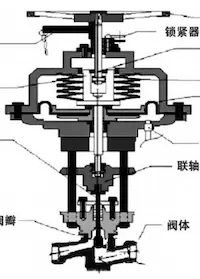
1.1 Structure of Pneumatic Globe Valves
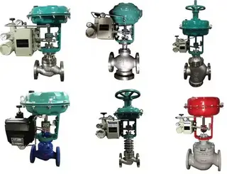
The most common types of pneumatic globe valves are fail-to-close valves with handwheels, fail-to-open valves with handwheels, fail-to-close valves without handwheels, and fail-to-open valves without handwheels. In domestic nuclear power plants, the two most commonly used types are fail-to-close and fail-to-open valves, both equipped with handwheels.
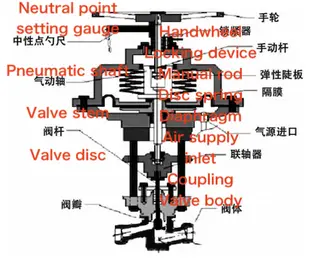
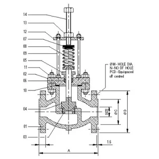
Figure 1 The structure of a typical pneumatic globe valve equipped with a handwheel
1.2 Working Principle of Pneumatic Globe Valves
Pneumatic globe valves are powered by compressed air and operated remotely, with control commands issued manually or automatically from the main control room, triggering the solenoid valve to supply or exhaust air to the diaphragm chamber. The compressed air acts on the diaphragm or piston, overcoming spring force and friction, and drives the valve stem and disc assembly to move upward or downward. For fail-to-open valves, air pressure closes the valve, while for fail-to-close valves, air pressure opens it, allowing the valve to regulate flow or achieve full shut-off. In nuclear power plant applications, pneumatic globe valves are usually fitted with a manual operating mechanism to maintain operability if the pneumatic system fails. Under normal operation, the manual mechanism is locked in a safe position that does not interfere with valve function, commonly called the neutral position. Valve opening and closing are typically controlled remotely from the main control room or local control stations. In emergencies—such as air supply loss or remote control failure—the manual mechanism can be used from the neutral position to open or close the valve as needed, or to lock it in a specified open or closed position according to system requirements. During operation, issues such as pneumatic actuator diaphragm leaks, incorrect manual mechanism adjustment, packing failure, improper on-site operation, or air supply abnormalities can significantly threaten the safe and stable functioning of nuclear power plants.
2. Typical Faults and Analysis of Pneumatic Globe Valves
In domestic nuclear power plants, pneumatic globe valves are mainly supplied by a French manufacturer. At projects including Hongyanhe, Ningde, Yangjiang, and Fangchenggang, reported failures include pneumatic actuator diaphragm leakage, vent hole leakage, inability to open or close, delayed valve operation, abnormal remote status signals, and packing leakage. Such failures can hinder the valves from fulfilling their intended system functions, seriously jeopardizing unit safety and failing to comply with nuclear safety standards.
2.1 Common Faults of Pneumatic Globe Valves
(1) Internal Valve Leakage
Sealing Surface Damage
The primary causes are the presence of foreign particles on the sealing surface, long-term erosion by the medium, and inherent material defects.
Insufficient Sealing Force
This is primarily caused by weakened disc spring force during operation, low air supply pressure or actuator chamber leakage, and disc spring breakage.
Incomplete Sealing Surface Contact
This can result from assembly misalignment, incorrect neutral point adjustment, or foreign matter trapped on the sealing surface.
(2) Leakage Between the Valve Body and Bonnet
Cause Analysis:
Damaged gasket, insufficient torque on bonnet bolts, or compromised sealing weld layer.
Corrective Measures:
Replace the gasket, check and adjust the bolt torque, and re-weld the sealing layer if needed.
(3) External Leakage at the Packing
Cause Analysis:
Packing damage or insufficient torque applied to the packing gland.
Corrective Measures:
Replace the packing and retighten the packing gland to the specified torque.
(4) Incorrect Neutral Point Setting
During maintenance and operation, the valve’s neutral position may shift due to internal repairs (e.g., grinding of the valve disc or seat), actuator maintenance or diaphragm replacement, high-pressure sealing tests, loosening of stem components or actuator support bolts, wear from repeated valve disc–seat impact, or improper manual operation on site.
Corrective measure:
Reset and calibrate the valve’s neutral point.
(5) Pneumatic Circuit Faults
The pneumatic circuit supplies the external driving force for valve operation, and any malfunction can cause the valve to become inoperable or exhibit abnormal opening and closing behavior. Typical faults include incorrect air supply pressure, clogged filters, solenoid valve malfunctions, and air leaks at pipeline connections. Circuit pressure can be monitored on the pneumatic control panel’s pressure gauge and should be maintained at 4.0 ± 0.1 bar. Excessive pressure accelerates diaphragm wear, whereas insufficient pressure can cause incomplete or slow valve operation. These problems can be resolved by adjusting the pressure-reducing valve, cleaning or replacing filters, replacing malfunctioning solenoid valves, or repairing leaking connections.
(6) Valve Opening and Closing Timeout
Cause analysis:
Insufficient solenoid valve air supply or exhaust capacity, excessively low air pressure, blocked air lines, overly tight packing, or jamming between the valve disc and stem.
(7) Abnormal Remote Opening/Closing Signal Indication
Cause analysis:
Electrical circuit failure or limit switch malfunction, including incorrect switch positioning, microswitch failure, wiring defects, or DCS card malfunction.
Corrective measures:
Adjust or replace the limit switch, check the wiring, and verify the functionality of the instrumentation control card.
Table 1 Common Faults of Pneumatic Globe Valves and Countermeasures
|
Fault Phenomenon |
Cause Analysis |
Solution |
|
Internal leakage |
Sealing surface damage |
Grind or replace valve disc/seat |
|
Foreign matter on sealing surface |
Flush or disassemble and inspect |
|
|
Disc spring misadjustment or fracture |
Re-adjust or replace disc spring |
|
|
Low air supply pressure |
Adjust pressure reducing valve |
|
|
Solenoid valve exhaust failure |
Inspect or replace solenoid valve |
|
|
Pneumatic actuator leakage |
Re-tighten or reassemble actuator |
|
|
Leakage at body/bonnet |
Seal weld failure |
Grind and re-weld |
|
Insufficient bolt torque |
Re-tighten to specification |
|
|
Packing leakage |
Insufficient packing torque |
Re-tighten packing |
|
Packing failure |
Replace packing |
|
|
Valve movement abnormal |
Excessive packing tightness |
Re-adjust packing torque |
|
Incorrect stroke limit |
Re-adjust stroke limit nut |
|
|
Excessive stem friction |
Inspect actuator, replace seals |
|
|
Actuator air leakage |
Diaphragm rupture |
Replace diaphragm |
2.2 Specific Case Analysis
2.2.1 Diaphragm Leakage Case and Analysis
At a nuclear power plant in China, approximately 20 pneumatic globe valves—including RIS208/209VP, RPE002VY, RPE055VE, RCP150/250/350VD, and REN124VP—suffered diaphragm deformation, leading to sealing failure and air leakage, with an overall failure rate of nearly 14%. On-site disassembly and inspection revealed that the diaphragms of the failed valves gradually deformed during repeated opening and closing cycles. The primary deformation zone was located on the curved surface between the three bolts adjacent to the instrument air inlet, as shown in Figure 2. Further inspection revealed misalignment of the diaphragm locking bolt holes, wear on the contact surfaces, and deformation of the bolt holes themselves. The failure symptoms, structural design, and supplier were essentially identical across all affected valves, indicating a common-mode failure. Diaphragm deformation resulted in a significant reduction in sealing performance, preventing the air pressure in the actuator chamber from reaching the required setpoint. As a result, multiple operational and system-level issues occurred, including the inability to remotely and automatically open or close the valve, valve opening times exceeding allowable limits, and inadequate pipeline sealing after valve closure.
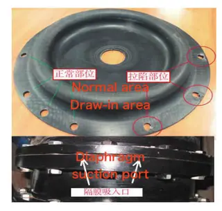
Figure 2 Schematic diagram of a deformed diaphragm
2.2.2 Case Study and Analysis of Air Leakage from Pneumatic Actuator Vent Holes
During a major overhaul at a domestic nuclear power plant, air leakage was detected at the vent holes of the pneumatic actuators on several pneumatic globe valves, including RPE002VY, RPE055VE, and RIS209VP. This leakage prevented adequate pressure buildup in the actuator chamber, rendering remote control of air supply and exhaust via command signals ineffective and ultimately impairing normal valve opening and closing.
Disassembly and inspection of the failed valves revealed the following root causes of air leakage from the pneumatic actuator vent holes:
Insufficient tightening torque of the diaphragm cover locking nut during assembly
Dimensional deviations in the diaphragm compensation ring, leading to insufficient diaphragm compression
Scratching or damage to the O-ring during installation
Aging and permanent deformation of the O-ring material
Corrective measures included replacing the O-rings, verifying the dimensions of the compensation ring and diaphragm, ensuring the actuator cover was tightened to the specified torque, replacing any damaged diaphragms, and reassembling the pneumatic actuator according to standard procedures.
2.2.3 Case Study and Analysis of Cracking in Pneumatic Globe Valve Discs
During maintenance at a domestic nuclear power plant, 11 pneumatic globe valves were inspected, revealing cracks on the sealing surfaces of six valve discs. The crack morphologies of representative valve discs are shown in Figure 3. Specifically, RIS206/124VP exhibited a T-shaped crack, while RIS208/209VP exhibited an I-shaped crack.
Failure analysis identified the following primary causes of valve disc cracking:
Nonconforming chemical composition of the Stellite alloy
The carbon content of the Stellite hardfacing alloy on the valve disc exceeded the specified limit and did not comply with the requirements of RCC-M S8000. The elevated carbon content increased the brittleness of the material and reduced its tensile strength, making the valve disc more susceptible to cracking.
Improper hardfacing welding process
The supplier applied Stellite hardfacing to the valve disc using manual oxyacetylene welding. This process is susceptible to excessive carburization, leading to increased brittleness of the hardfacing layer and reduced compressive strength.
Improper on-site operation leading to overload
Excessive force applied to the handwheel by on-site personnel after valve closure imposed overload stress on the valve disc. As a result, the applied load exceeded the supplier-specified design limit of the valve disc (800 N/mm). Although the ultimate load capacity of Stellite 12 hard alloy is approximately 1600 N/mm, the combined effects of material brittleness and welding-induced degradation caused the valve disc to crack under the applied overload.
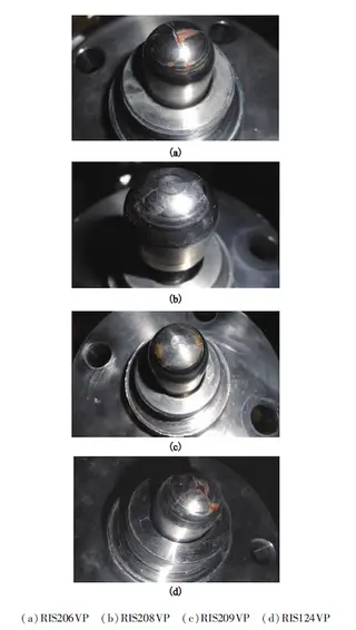
Figure 3. Macroscopic view of cracks on the sealing surfaces of representative valve discs
3. Fault Diagnosis and Equipment Protection Standardization for Pneumatic Globe Valves
Based on the analysis of common failures in pneumatic globe valves from a French manufacturer and practical experience from on-site installation, commissioning, and maintenance, a standardized procedure for equipment protection has been developed.
3.1 Standardization of Pneumatic Actuator Maintenance
Among the various pneumatic actuator failures, actuator inaction is one of the most common, with diaphragm leakage being the primary cause. On-site investigations show that insufficient or uneven bolt tightening is a major contributor to diaphragm leakage, and implementing standardized maintenance practices can effectively prevent this issue.
This section outlines precise bolt tightening methods and standardizes the maintenance procedure, offering technical guidance for installation, commissioning, and commercial operation. The specific requirements are as follows:
All bolts must be tightened using a torque wrench, following the “cross-tightening method” to determine the proper sequence.
As illustrated in Figure 4, the pneumatic actuator diaphragm cover is fastened with 16 bolts, each with a specified design torque of 30 N·m. Tightening should be performed in three stages:
First stage: 10 N·m
Second stage: 20 N·m
Third stage: 30 N·m
Tightening should follow the specified cross sequence until all bolts are secured. During the final stage, with the torque wrench set to the design torque, each bolt must be tightened only once. Bolts that have already reached the specified torque must not be re-tightened.
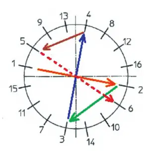
Figure 4 Schematic diagram of bolt tightening using the cross-tightening method
3.2 Standardization of Finished Product Protection
Analysis of pneumatic actuator failures identified five primary contributing factors:
Improper storage and handling – e.g., placing disassembled pneumatic actuators directly on the ground without adequate protection.
Incorrect installation – e.g., interference from air intake pipelines blocked by brackets, causing stress deformation of the pipelines.
Improper operation by personnel – e.g., altering original equipment settings, such as torque values.
Inadequate equipment cleaning – e.g., accumulation of debris and bolt corrosion, leading to valve stem jamming and air intake line blockage.
Non-compliance with operating procedures – e.g., failing to remove the valve position indicator locking pin during operation, causing deformation or damage to the indicator rod.
To mitigate quality issues caused by improper on-site handling, a quality protection and inspection standard for pneumatic globe valves was developed and validated through practical implementation. This standard defines critical inspection and protection points at each stage after the valve arrives on site. It enables early detection of potential equipment defects, rapid identification of key protection measures, and provides guidance to ensure equipment quality throughout installation, commissioning, and operation.
3.3 Pneumatic Globe Valve Fault Diagnosis Method
Based on potential failure modes and established standardized procedures for pneumatic valves in nuclear power plants, combined with an analysis of common faults in French-supplied pneumatic globe valves, a systematic fault diagnosis methodology is proposed. This method offers systematic guidance for installation, commissioning, and maintenance at all on-site stages. When applied during commissioning at a domestic nuclear power plant, it significantly shortened the time required for fault identification and localization. Its application in other nuclear projects optimized commissioning schedules and enabled timely resolution of issues such as automatic opening/closing failures and excessive operating times, serving as a valuable reference for future installation and commissioning work.
4. Conclusion
This paper investigates typical faults of French-supplied pneumatic globe valves in domestic nuclear power plants, summarizes common failure modes in CPR1000 units, and proposes a comprehensive fault diagnosis approach and standardized maintenance and protection procedures. These methods can be applied throughout installation, commissioning, and operation, providing effective diagnostic tools and valuable practical experience for ensuring valve reliability. Based on actual on-site conditions, practical solutions are proposed, offering valuable guidance for addressing similar issues in China’s improved million-kilowatt CPR1000 nuclear power plants.
Send your message to this supplier
Related Articles from the Supplier

Related Articles from China Manufacturers

Routine Maintenance and Fault Analysis of Pipeline
- Oct 31, 2022
Analysis of Hydraulic Cylinder Leakage Faults
- Apr 22, 2024
Related Products Mentioned in the Article
Supplier Website
Source: https://www.baltic-valve.com/fault-analysis-and-diagnosis-of-pneumatic-globe-valves-in-nuclear-power-plants.html