Design and Implementation of an Automatic Coaxiality Adjustment Device for Mining Spherical Gate Valves
Abstract
This paper presents the design of an automatic coaxiality detection and adjustment system developed for the ball and seat geometry of a mining spherical gate valve. The device incorporates an automated tightening mechanism that repeatedly tightens or loosens the two dustproof end caps, allowing the system to adjust the ball’s position within the valve seat. The end caps are incrementally tightened until the ball and valve seat become fully concentric, thereby completing the automatic coaxiality adjustment of the mining spherical gate valve.
Introduction
A wide range of mining gate valves is currently available on the market, and they are primarily used in hydraulic control systems for mining operations. These products are assembled entirely by hand, and for larger-diameter mining gate valves, the key components—the valve seat and the ball—are comparatively heavy. Currently, coaxiality adjustment between the ball and valve seat is performed manually. This method has low precision, and the resulting assembly quality directly affects the performance of the mining gate valve. In addition, the adjustment and assembly process is labor-intensive and inefficient, resulting in wasted resources, low productivity, and extended product assembly cycles. Manual coaxiality adjustment of the ball and valve seat involves placing the lower follower bearing of the coaxiality adjustment fixture against the inner surface of the valve seat and positioning the dial indicator probe in contact with the ball. The probe is then moved along the entire inner circumference of the valve seat, and the dial indicator readings indicate the deviation between the ball and the center of the valve seat. During this process, the left and right dustproof end caps must be repeatedly tightened or loosened to reposition the ball and gradually bring it into alignment. The end caps are progressively tightened until coaxiality is achieved. To overcome the limitations of manual assembly, an automatic adjustment device for mining spherical gate valves was developed, offering an innovative alternative to conventional adjustment methods. With a single-button start, the device automatically performs the coaxiality adjustment of the ball and valve seat, providing fast, high-precision adjustment and significant practical value in enhancing the automation of ball gate valve assembly. A high-precision displacement sensor continuously monitors the coaxiality of the ball and valve seat, providing real-time feedback on both the alignment and the adjustment process. The system uses a servo motor equipped with a reducer and torque sensor to repeatedly tighten the two dustproof end caps at a controlled torque, thereby adjusting the position of the ball. The end caps are gradually tightened until the specified torque is achieved, ensuring precise and consistent adjustment. The device integrates high-precision displacement and torque sensors to collect, record, and analyze data on coaxiality adjustments and the tightening torque of the dustproof end caps. This data serves as a basis for optimizing the assembly process parameters of mining spherical gate valves.
1. Device Structural Design and Key Selection Calculations
The device consists of a displacement mechanism, a secondary positioning mechanism, a clamping and measurement mechanism, left and right coaxiality adjustment mechanisms, a lower platform assembly, and an equipment cover assembly. The overall structural layout of the device is shown in Figure 1.

Figure 1: Overall Device Design
1.1 Displacement Mechanism and Secondary Positioning Mechanism
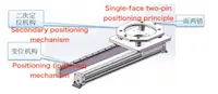
The pre-assembled mining spherical gate valve, including the valve seat, ball, and dustproof end caps, is first placed onto the secondary positioning mechanism of the coaxiality adjustment device. The valve is positioned using a single-side dual-pin positioning principle. Driven by a pneumatic cylinder, the displacement mechanism moves the secondary positioning mechanism—along with the ball valve—to the clamping and measurement position, as shown in Figure 2.
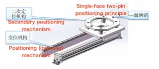
Figure 2: Displacement Mechanism and Secondary Positioning Mechanism
1.2 Pressing and Measurement Mechanism
In the pressing and measurement mechanism, a cylinder drives the measuring unit downward to make contact with the upper surface of the valve seat. Two sliding cylinders then extend the probes of the displacement sensors until they contact the surface of the ball, at which point the coaxiality deviation between the ball and the valve seat is measured. The structure of the pressing and measurement mechanism is shown in Figure 3. The mechanism is equipped with two high-precision displacement sensors, and a pair of follower bearings is used to position the upper surface of the valve seat as well as the left and right sides of its inner circular surface. Once positioning is complete, the displacement sensor probes extend to contact the ball’s surface, allowing accurate measurement of the coaxiality deviation between the ball and the valve seat.
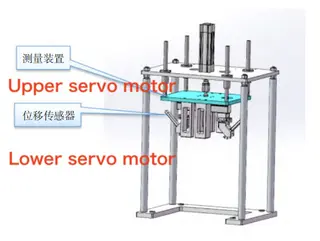
Figure 3. Pressing and Measurement Mechanism
1.3 Coaxiality Adjustment Mechanism
The left and right coaxiality adjustment mechanisms are activated simultaneously by the lower servo motors. As the displacement mechanisms move toward the center, the upper servo motors rotate, driving the front ends of the shafts to turn the tooling fixtures, which engage with the dustproof end caps on both sides of the mining spherical gate valve. The displacement sensors measure the coaxiality deviation between the ball and the valve seat. The system then analyzes the measured offset and uses software logic to calculate the required displacement. The lower servo motors then move the left and right coaxiality adjustment mechanisms further toward the center, while the upper servo motors rotate the shafts to tighten the dustproof end caps. During the adjustment process, the dustproof end caps are continuously rotated—tightened or loosened as needed—to adjust the ball’s position within the valve seat. The two dustproof end caps work together to reposition the ball, gradually tightening until the ball’s center aligns with the center of the valve seat. Once the end caps reach the rated tightening torque—monitored by the torque sensor at the front rotation axis of the upper shaft—the coaxiality adjustment of the mining spherical gate valve is complete. The left and right coaxiality adjustment mechanisms are illustrated in Figures 4 and 5.
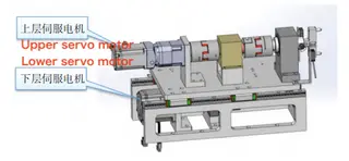
Figure 4. Left Coaxiality Adjustment Mechanism
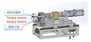
Figure 5. Right Coaxiality Adjustment Mechanism
Each coaxiality adjustment mechanism is equipped with a high-precision torque sensor that monitors torque in real time, ensuring the dustproof end caps reach the specified rated torque during tightening. If the torque exceeds the limit, the upper servo motor reverses to slightly loosen the end cap and then retightens it until the torque is within the acceptable range. Throughout the adjustment process, the displacement sensor readings are transmitted in real time to the control system. Using software logic, the system calculates and executes the required displacements of the left and right servo motors until the ball and valve seat achieve the specified coaxiality tolerance.
1.4 Key Component Selection and Calculations
The upper servo motor and reducer, which act as the drive actuators for the adjustment mechanisms, are critical components of this device.
Operating Requirements:
Dustproof end cap mass: m = 0.46 kg
Radius: r = 30 mm
Start-up time: t = 0.5 s
Rotation speed: n = 60 r/min
Required tightening torque: T = 10 N·m
The angular acceleration of the dustproof end cap is calculated as:
JL=0.5mr2 =2×10⁻⁴kg·m2
The moment of inertia of the dustproof end cap is:
α=2π×n/(60t)=12.56rad/s2
The starting torque at the load end consists of two parts: the rotational torque of the end cap TS1 and the torque to overcome friction TS2.
TS1=JLα=0.0025N·m
TS2=μmgr=0.0203N·m
TS=TS1+TS2=0.0228N·m
Compared with the required locking torque of 10 N·m, the starting torque and the moment of inertia at the load end are negligible. Therefore, the selection of the motor and reducer is primarily determined by the required tightening torque. A Panasonic MHMF042L1U2M motor, rated at 1.27 N·m, is selected and paired with a 20:1 reducer (model AB60L2-20-P1-S2-14-30-50-70-M4). This combination delivers an output torque of 25.4 N·m at the drive end, providing a safety margin of approximately 2.5×, making it a suitable choice.
2. Actual Application Results
Before formal production, the device performed five automatic coaxiality adjustments on spherical stop valves of four diameters (40, 60, 80, and 100 mm), producing a total of 20 sets of adjustment data, as summarized in Table 1.
Table 1: Coaxiality Measurement Results of Spherical Stop Valves (mm)
|
Valve Diameter |
Measurement 1 |
Measurement 2 |
Measurement 3 |
Measurement 4 |
Measurement 5 |
|
40 |
0.01 |
0.02 |
0.01 |
0.02 |
0.02 |
|
60 |
0.01 |
0.02 |
0.01 |
0.01 |
0.01 |
|
80 |
0.02 |
0.02 |
0.02 |
0.01 |
0.01 |
|
100 |
0.01 |
0.01 |
0.02 |
0.01 |
0.02 |
From the data in Table 1, it can be concluded that the device achieves an automatic coaxiality adjustment with an accuracy of better than 0.02 mm. The device has successfully completed design, fabrication, debugging, and field testing, meeting all performance targets established during the design phase. The built device is shown in Figure 6.
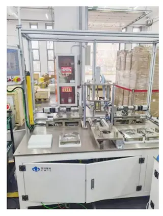
Figure 6. Photograph of the Completed Device
3. Conclusion
The automatic adjustment device for mining spherical gate valves transforms the traditional manual assembly and adjustment process into a fully automated operation. It rapidly performs coaxiality adjustments of the ball and valve seat with high precision, achieving alignment within 0.02 mm, and provides a valuable reference for the automated assembly and coaxiality adjustment of ball gate valves.
Send your message to this supplier
Related Articles from the Supplier

Related Articles from China Manufacturers


Related Products Mentioned in the Article
Supplier Website
Source: https://www.baltic-valve.com/design-and-implementation-of-an-automatic-coaxiality-adjustment-device-for-mining-spherical-gate-valves.html